



Attention:
on vehicles with SRS system:
- - When removing and installing the instrument panel and steering wheel, refer to the instructions for removing and installing the driver's front airbag, SRS coil wire, and passenger's front airbag in the "Supplemental Restraint System (SRS)" chapter.
- - When removing and installing the instrument panel, do not allow it to hit the SRS electronic control unit.
Removal and installation
− The parts are removed in the order of the numbers indicated in the figure "Removing the instrument panel".
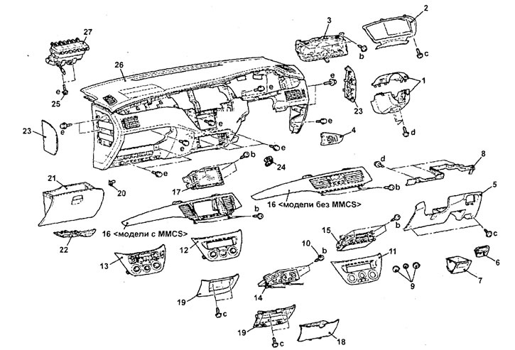
Removal the instrument panel. 1 - Steering column cover, 2 - Instrument cluster trim, 3 - Instrument cluster, 4 - Driver's side instrument panel trim, 5 - Driver's side lower instrument panel trim, 6 - Stowage compartment, 7 - Additional compartment, 8 - Driver's side lower instrument panel trim mounting bracket, 9 - Heater and air conditioning control panel switch knobs, 10 - Heater and air conditioning control panel mounting screw, 11 - Manual heater and air conditioning control panel (models without MMCS), 12 - Automatic heater* and air conditioning control panel (models without MMCS), 13 - Automatic heater and air conditioning control panel (models with MMCS), 14 - Heater control panel (models without air conditioning), 15 - Radio, 16 - Instrument panel center trim, 17 - Multifunction display, 18 - Additional storage compartment trim in the lower part of the instrument panel center trim, 19 - additional storage compartment in the lower part of the instrument panel center trim or the lower part of the instrument panel center trim, 20 - storage compartment opening stroke limiter, 21 - storage compartment, 22 - lower instrument panel trim on the passenger side, 23 - instrument panel side cover, 24 - air temperature sensor in the vehicle interior, 25 - front passenger airbag module mounting bolt (unscrew the steering column and steering shaft mounting bolt), 26 - instrument panel assembly, 27 - front passenger airbag module.
- (Station wagon) When removing parts, pay attention to the operation of removing the front passenger airbag module.
Disconnect the negative battery cable and use two screwdrivers to carefully pry up the retaining clips and remove the passenger front airbag module.
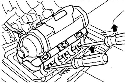
− Installation of parts is carried out in the reverse order of removal.
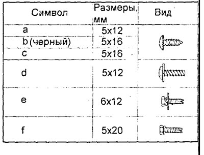
Table. Dimensions of instrument panel mounting bolts and screws.
Disassembly and assembly
− Disassembly is carried out in the order of the numbers indicated in the figure "Dashboard disassembly".
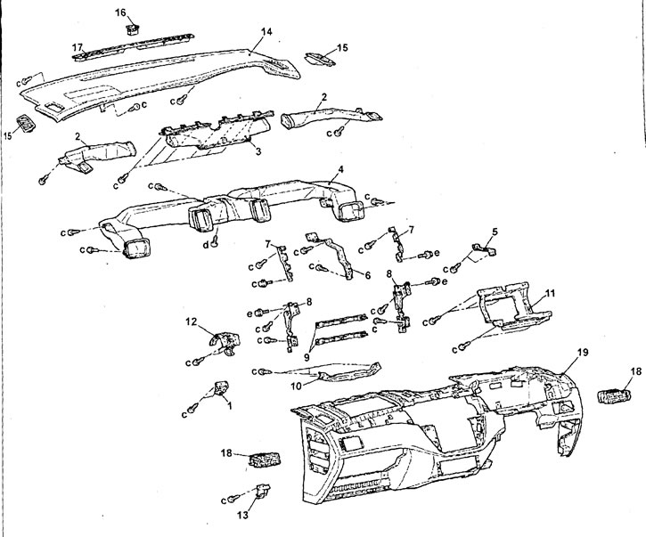
Disassembling the instrument panel. 1 - Side instrument panel mounting bracket (left), 2 - Side window heating duct, 3 - Windshield heating duct, 4 - Distribution duct, 5 - Side instrument panel mounting bracket (right), 6 - Central instrument panel mounting bracket, 7 - Instrument panel central trim mounting bracket (models with MMCS), 8 - Instrument panel longitudinal stiffener, 9 - Instrument panel transverse stiffener, 10 - Side instrument panel stiffener, 11 - Multifunction display mounting bracket (models with MMCS), 12 - Glove compartment lock retainer, 13 - Glove compartment trim, 14 - Instrument panel upper trim, 15 - Side window deflector, 16 - Sun sensor, 17 - Windshield deflector, 18 - Side deflector with trim assembly, 19 - Instrument panel.
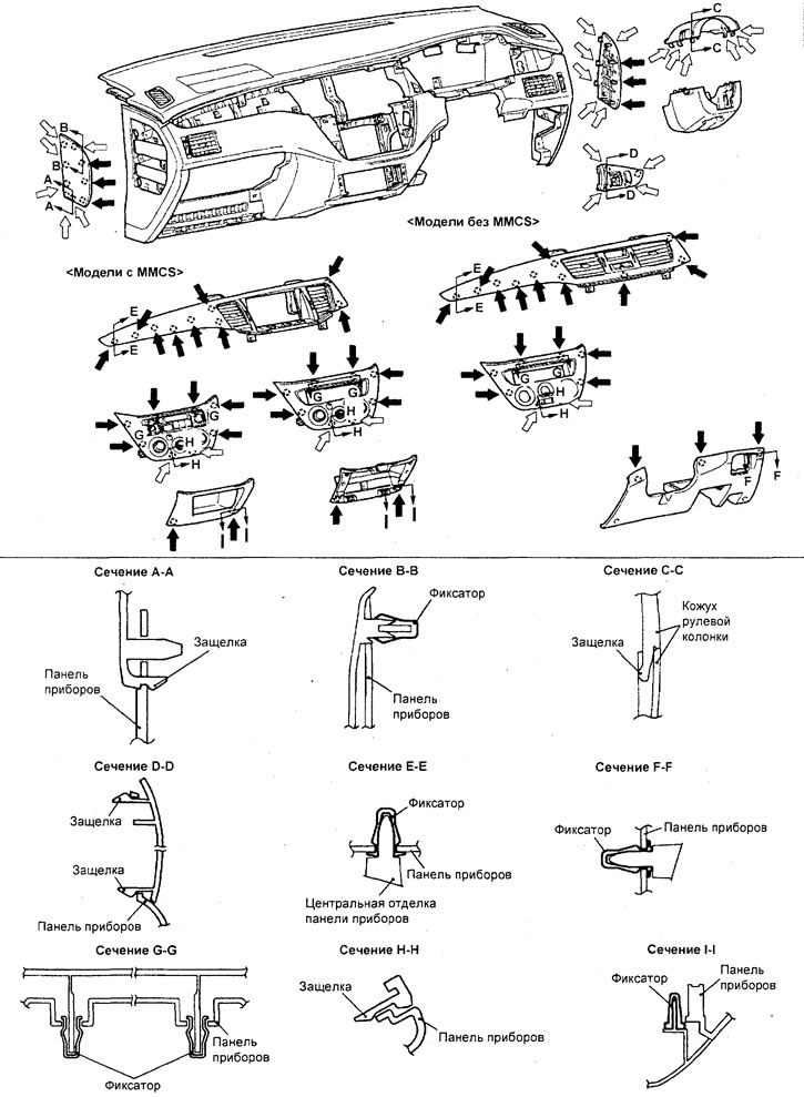
Location of instrument panel component fasteners, latches and bolts.
Note: with arrows "
 "the locations of the plastic fasteners are indicated; arrows "
 "The locations of the latches are shown.
- Assembly is carried out in the reverse order of disassembly.