Contents: Lubrication points ⤓ Installing the steering rod on the…⤓ Installing the clamp ⤓ Installing the mounting rubber…⤓
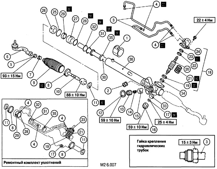
Elements of the steering mechanism design (for left-hand drive vehicles): 1. Steering gear rubber mounting bushing; 2. Mounting rubber-metal bushing for fastening the steering gear; 3. Pipes for supplying (draining) oil to the power steering hydraulic cylinder; 4. Sealing ring (replace with a new one during assembly); 5. Lock nut; 6. Tie rod end; 7. Anther clamp (replace with a new one during assembly); 8. Anther clamp (replace with a new one during assembly); 9. Corrugated steering rod boot; 10. Steering rod; 11. Lock washer (replace with a new one during assembly); 12. Lock nut; 13. Threaded cap regulating shoe pressure on the rack; 14. Spring; 15. Rack support shoe; 16. Threaded plug; 17. Lock nut (replace with a new one during assembly); 18. Control valve assembly; 19. Lower oil seal (replace with a new one during assembly); 20. Gear and valve assembly; 21. Sealing ring (replace with a new one during assembly); 22. Upper bearing; 23. Upper oil seal (replace with a new one during assembly); 24. Valve body; 25. Snap ring; 26. Support stopper (replace with a new one during assembly); 27. Support bushing assembly; 28. Sealing ring (replace with a new one during assembly); 29. Oil seal (replace with a new one during assembly); 30. Steering rack assembly; 31. Sealing ring (replace with a new one during assembly); 32. Sealing ring; 33. Lower bearing (replace with a new one during assembly); 34. Needle bearing; 35. Oil seal (replace with a new one during assembly); 36. Steering gear housing
Disassembly is carried out in the order shown in Fig. M2 6.007. Assembly is carried out in the reverse order of disassembly.
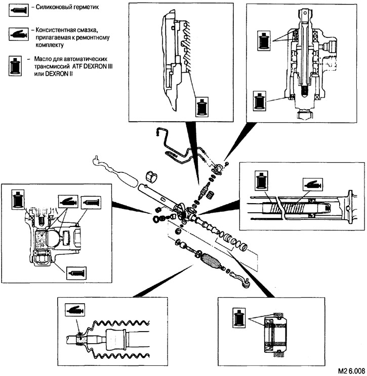
Lubrication points
Installing the steering rod on the rack
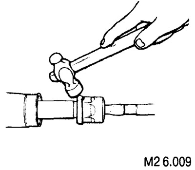
After connecting the steering rod to the rack, use a hammer to bend the edges of the washer, fixing the hexagon of the inner joint housing of the steering rod.
Installing the clamp
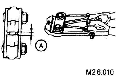
The clamping clamps are fixed using a special crimping tool (such as shown in Fig. M2 6.010).
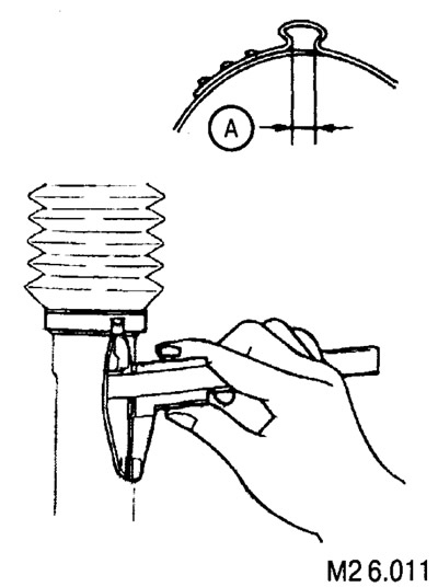
When properly fixed, the corrugation size A should be between 2.4 mm and 2.8 mm.
Installing the mounting rubber bushing
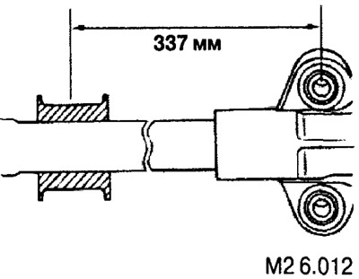
Fig. M2 6.012 shows the correct position of the mounting rubber bushing.