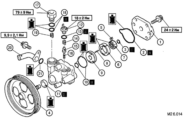
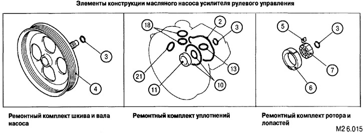
The list of structural elements of the power steering oil pump for drawings M2 6.014-M2 6.015: 1. Oil pump cover. 2. O-ring (replace with a new one when reassembling). 3. Snap ring (replace with a new one when reassembling). 4. Oil pump pulley. 5. Rotor blade. 6. Shell with internal figured profiling. 7. Rotor. 8. Pin. 9. Thrust plate. 10. O-ring (replace with a new one when reassembling). 11. Oil seal (replace with a new one when reassembling). 12. Terminal assembly. 13. O-ring (replace with a new one when reassembling). 14. Spring. 15. Plunger. 16. Piston rod assembly. 17. Repair kit for connecting the pressure pipe to the pump. 18. O-ring (replace with a new one when reassembling). 19. Spring-flow regulator. 20. Supply hose connection repair kit. 21. O-ring (replace with a new one when reassembling).
Disassembly is carried out in the order indicated in Fig. M2 6.014.
Assembly is carried out in the reverse order of disassembly.
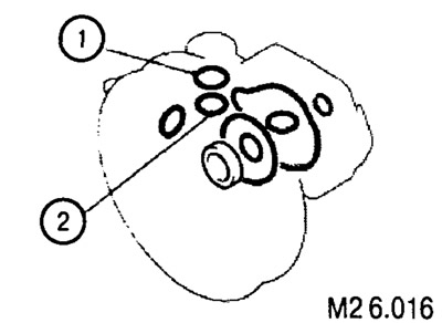
O-rings
O-rings 1 (see fig. M2 6.016) have a width of 2.4 mm and an internal diameter of 17.8 mm.
O-rings 2 (see fig. M2 6.016) have a width of 1.5 mm and an internal diameter of 13.5 mm.
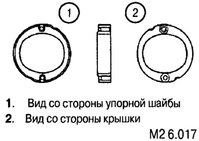
Installation of a shell with internal figured profiling