



Contents: Removal ⤓ Pre-installation check ⤓ Disassembly ⤓ Pre-assembly check ⤓ Assembling the pump ⤓ Installation ⤓
Removal
− Before removing parts, drain the power steering fluid from the hydraulic system.
− The parts are removed in the order of numbers shown in the figure "Power steering pump".
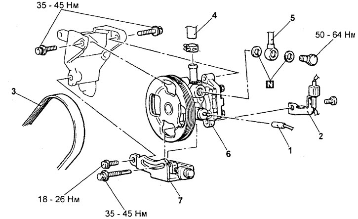
Power steering pump (models with 4G15 engines). 1 - connector of the sensor of the switch for the fluid pressure in the hydraulic system of the booster, 2 - bracket of the air conditioning compressor wiring harness, 3 - drive belt 4 - inlet hose, 5 - discharge hose, 6 - hydraulic booster pump 7 - bracket of the hydraulic booster pump.
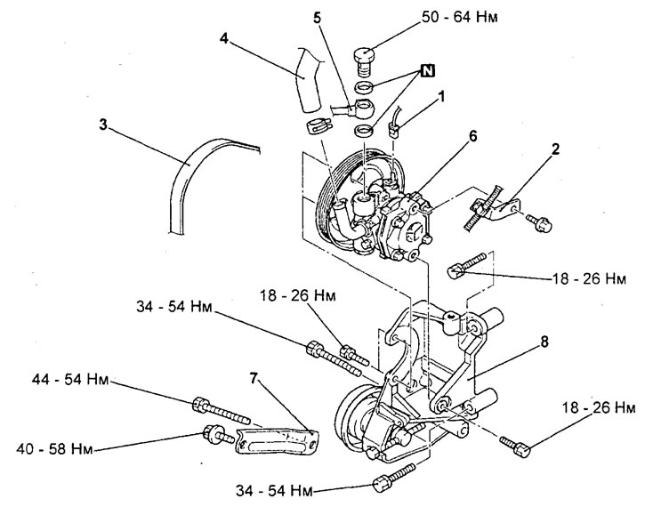
Power steering pump (models with 4G93 engines). 1 - connector of the sensor-switch for the fluid pressure in the hydraulic system of the booster, 2 - bracket of the air conditioning compressor wiring harness, 3 - drive belt, 4 - inlet hose, 5 - discharge hose, 6 - hydraulic booster pump, 7 - bracket plate, 8 - bracket of the hydraulic booster pump.
− When removing parts, pay attention to the operation of removing the power steering pump assembly.
Remove the A/C compressor mounting bolt and disconnect the A/C compressor, then remove the pump assembly.
Caution: Do not disconnect the air conditioning system pipes from the air conditioning compressor when performing this operation.
Pre-installation check
1. Check the drive belt for cracks.
2. Check for imbalance when rotating the pulley assembly.
Disassembly
− The parts are removed in the order of numbers shown in the figure "Disassembling the power steering pump".
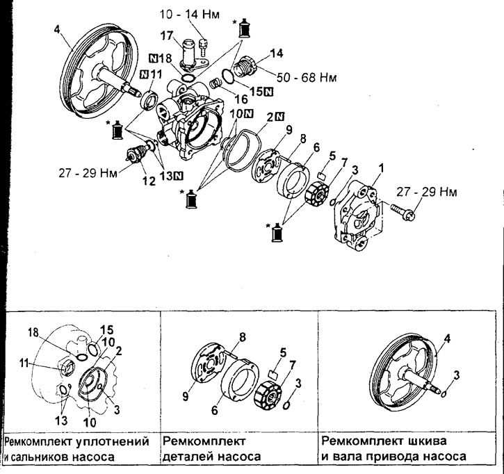
Disassembling the power steering pump (models with 4G 15 engines). 1 - pump cover, 2 - ring gasket, 3 - retaining ring, 4 - pulley and pump drive shaft, 5 - blade, 6 - cam washer, 7 - rotor, 8 - lock pin, 9 - side plate, 10 - ring gaskets, 11 - oil seal, 12 - sensor-switch for fluid pressure in the hydraulic system of the booster, 13 - ring gaskets, 14 - plug, 15 - ring gasket, 16 - flow control spring, 17 - connecting pipe of the inlet hose, 18 - ring gasket.
Caution: It is prohibited to disassemble the pressure switch sensor and valve assembly, as they are not disassemblable.
Note: Apply Mitsubishi ATF-SPII to the marked areas.

Disassembling the power steering pump (models with 4G93 engines). 1 - pump cover, 2 - ring gasket, 3 - retaining ring, 4 - pulley and pump drive shaft, 5 - blade, 6 - cam washer, 7 - rotor, 8 - lock pin, 9 - side plate, 10 - ring gaskets, 11 - oil seal, 12 - sensor-switch for fluid pressure in the hydraulic system of the booster, 13 - ring gaskets, 14 - plug, 15 - ring gasket, 16 - flow control spring, 17 - connecting pipe of the inlet hose, 18 - ring gasket.
Caution: It is prohibited to disassemble the pressure switch sensor and valve assembly, as they are not disassemblable.
Note: Apply Mitsubishi A TF-SPII to areas marked with "*".
Pre-assembly check
1. Check that the fluid flow control valve is not clogged.
2. Check the pulley assembly for wear or damage.
3. Check for "stepped" wear of the rotor blades and slots.
4. Check for "stepped" wear on the contact surface of the blades and cam washer.
5. Check the blades for damage.
Assembling the pump
- When installing the parts, pay attention to the following operations.
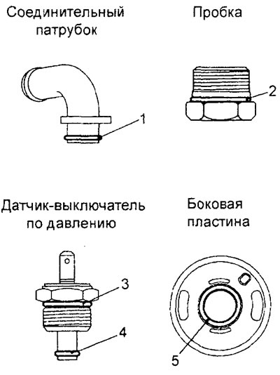
1. Installing O-rings.
Before installation, apply the recommended fluid to all O-rings, the sizes of O-rings are selected according to the table provided.
| Gasket number in the picture | Inner diameter x width, mm |
| 1 | 15.8 x 2.4 |
| 2 | 21.0 x 1.9 |
| 3 | 14.8 x 2.4 |
| 4 | 3.8 x 1.9 |
| 5 | 14.8 x 1.9 |
2. Installing the seal.
Using the special tool, install the oil seal as shown in the figure.
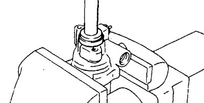
3. Installing the pump side plate Install the side plate by positioning it as shown in the figure.
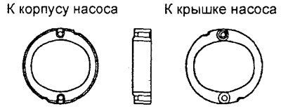
6. Installing the blades.
Install the blades into the rotor, paying particular attention to the correct installation direction.
Installation
− Installation of parts is carried out in the reverse order of removal.
The article is based on data from the website: mitsubishiman.ru
- After installing the parts, perform the following operations.
a) Fill the power steering hydraulic system with working fluid.
b) Adjust the tension of the power steering pump drive belt.
c) Bleed the power steering hydraulic system.