



Contents: Removal ⤓ Disassembling the steering mechanism ⤓ Pre-assembly check ⤓ Other checks. ⤓ Assembly ⤓ Pre-installation check ⤓ Installation ⤓
Removal
Caution: On models with the Supplemental Restraint System (SRS), set the front wheels to the straight-ahead position and remove the key from the ignition before removing the steering gear. Failure to do so may damage the SRS coil wire and cause the airbag to deploy unexpectedly, resulting in serious injury.
The parts are removed in the order of numbers shown in the figure "Steering mechanism".
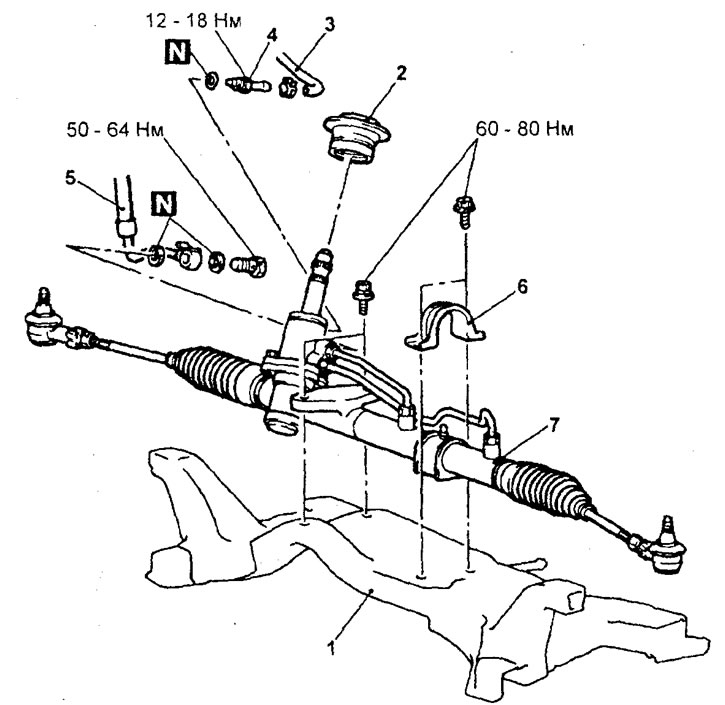
Steering gear. 1 - subframe, 2 - spacer, 3 - return hose connection, 4 - return pipe, 5 - delivery hose connection, 6 - steering gear mounting bracket, 7 - steering gear assembly.
Before removing parts, drain the power steering fluid from the hydraulic system.
When removing parts, pay attention to the following operations.
1. Disconnecting the steering rod end from the steering knuckle.
Attention:
- To prevent the puller from bouncing off, it must first be tied with a cord.
- Just loosen the mounting nut on the ball joint pin, do not unscrew the nut completely.
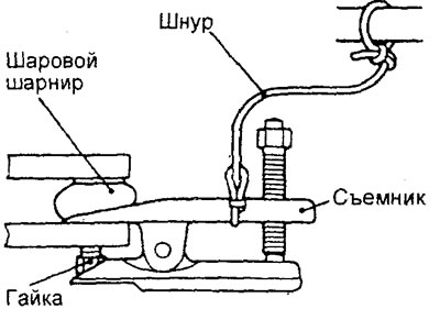
2. Removing the steering gear assembly.
Caution: When removing the steering gear assembly, remove the steering gear slowly and very carefully to avoid damaging the tie rod end boots and the ball joint boots of the tie rod ends.
Disassembling the steering mechanism
− The parts are removed in the order of numbers indicated in the figure "Disassembling the steering mechanism".
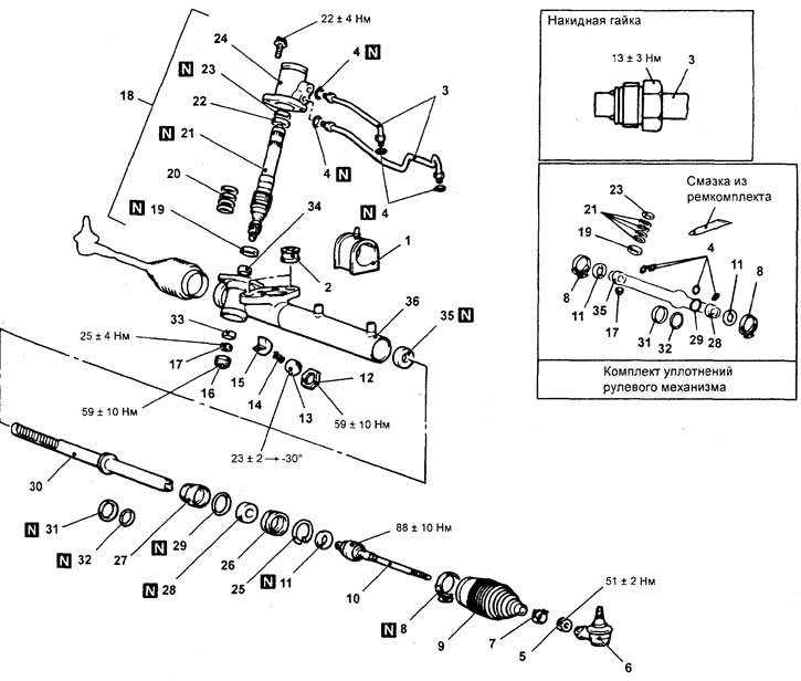
Disassembling the steering mechanism.1 - steering gear housing support bushing, 2 - steering gear housing side support bushing, 3 - pressure tube, 4 - ring gasket, 5 - lock nut, 6 - tie rod end, 7 - protective boot clamp, 8 - protective boot band clamp, 9 - protective boot, 10 - tie rod, 11 - lock washer (adjust the total torque of the pinion gear during installation), 12 - lock nut, 13 - rack stop cover, 14 - rack stop spring, 15 - rack stop, 16 - end plug, 17 - lock nut, 18 - valve housing assembly, 19 - lower oil seal, 20 - sealing rings, 21 - pinion gear and valve assembly, 22 - upper bearing, 23 - upper oil seal, 24 - valve body, 25 - retaining ring, 26 - rack travel limiter, 27 - rack support sleeve, 28 - oil seal, 29 - ring gasket, 30 - rack assembly, 31 - piston ring, 32 - ring gasket, 33 - lower bearing, 34 - needle bearing, 35 - oil seal, 36 - steering gear housing.
When removing parts, pay attention to the following operations.
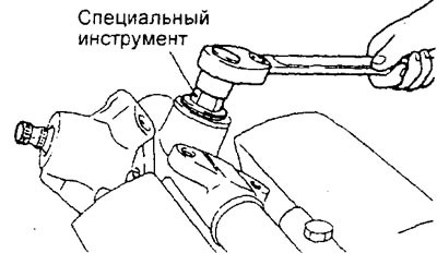
1. Removing the rack stop cover.
Using a special tool, remove the rack stop cover from the steering gear housing.
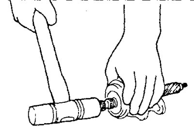
2. Removing the seal, drive gear and valve assembly.
Using light taps from a plastic-faced hammer, carefully remove the drive gear.
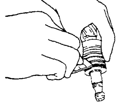
3. Removing the sealing rings.
Cut the O-ring and remove it from the pinion and valve assembly and from the rack.
Caution: When cutting the O-rings, be careful not to damage the pinion and valve assembly or rack.
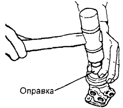
4. Removing the ball bearing and seal.
Using a drift and a plastic-faced hammer, simultaneously knock the seal and ball bearing out of the valve body.
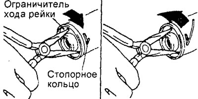
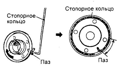
5. Removing the retaining ring.
a) Turn the rack travel stop clockwise until the end of the locking ring comes out of the groove in the steering gear housing.
b) Turn the rack travel stop counterclockwise and remove the retaining ring.
Caution: Please note that if you first turn the rack travel stop counterclockwise, the locking ring will rest against the groove in the steering gear housing and will not allow the rack travel stop to turn.
6. Removing the rack travel limiter, rack support sleeve, rack and seal.
a) Carefully remove the rack assembly and remove the rack travel stop and support sleeve at the same time.
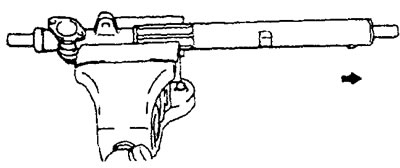
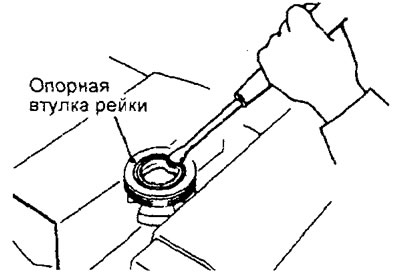
b) To remove the seal from the rack support sleeve, it is necessary to bend the seal slightly with a screwdriver.
Caution: Do not damage the sealing surface in the rack support sleeve.
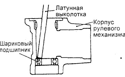
7. Removing the ball bearing.
To remove the ball bearing from the steering gear housing, use a special tool or a brass drift.
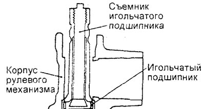
8. Removing the needle bearing.
Using a special tool, remove the needle bearing from the steering gear housing.
Caution: Do not open the special tool excessively to avoid damaging the inner surfaces of the steering gear housing.
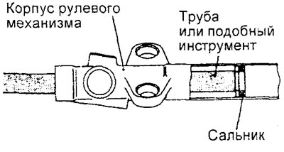
9. Removing the oil seal.
Using a suitable piece of pipe, remove the seal from the steering gear housing.
Caution: Do not damage the inner surface of the rack cylinder in the steering gear housing.
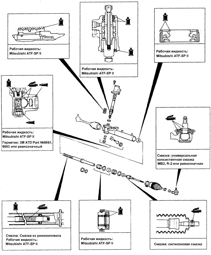
Map of application points for lubricant, working fluid and sealant.
Pre-assembly check
1. Steering rack.
a) Check the steering rack teeth for wear.
b) Check for excessive wear on the working surfaces of the seals.
c) Check the straightness of the steering rack.
2. Drive gear and valve assembly,
a) Check the pinion teeth for wear or damage.
b) Check the O-rings for wear or damage.
3. Bearing.
a) Check the smoothness of rotation and the absence of extraneous noise when the bearings are operating.
b) Check for play in the bearings.
c) Check that the needles do not fall out of the needle bearing.
Other checks.
a) Check the inner surface of the steering gear housing cylinder for damage.
b) Check the protective covers for wear, cracks and tears.
c) Check the rack stop for excessive wear or dents.
d) Check the steering rack support bushing for excessive wear or damage.
Assembly
Installation of parts is carried out in the reverse order of removal.
When installing the parts, please pay attention to the following operations.
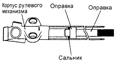
1. Installing the seal.
Perform the installation as shown in the figure.
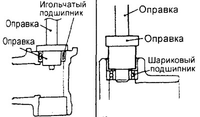
2. Installing the needle bearing and ball bearing.
Perform the installation as shown in the figure.
3. Installing the rack.
a) Lubricate the steering rack teeth with grease from the repair kit.
Caution: Do not plug the ventilation hole in the rack with grease.
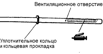
b) Cover the surface of the teeth with a special tool.
c) Lubricate the special tool with working fluid.
Recommended fluid - Mitsubishi ATF-SPII
Caution: Do not use ATF-SP II M and ATF-SP III fluid in the steering system.
d) Align the axes of the sealing ring hole and the steering rack to prevent the retaining ring from slipping out, and slowly insert the steering rack from the power cylinder side.
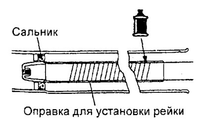
4. Installing the seal and the rack support sleeve.
a) Lubricate the outer surface of the seal with working fluid. Using a special device, press the seal flush with the end of the rack support sleeve.
Recommended fluid - Mitsubishi ATF-SP 11
Caution: Do not use ATF-SP II M and ATF-SP III fluid in the steering system.
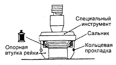
b) Lubricate the inner surface of the seal and the O-ring with working fluid.
Recommended fluid - Mitsubishi ATF-SP II
Caution: Do not use ATF-SP II M and ATF-SP III fluid in the steering system.
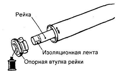
c) Wrap the end of the rail with insulating tape and place the support sleeve on the rail.
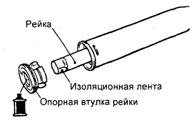
c) Wrap the end of the rail with insulating tape and place the support sleeve on the rail.
6. Installing the seal.
Lubricate the outer surface of the seal with working fluid. Using special tools, press the seal into the valve body.
Recommended Mitsubishi ATF-SP II fluid
Caution: Do not use ATF-SP I M and ATF-SP III fluid in the steering system.
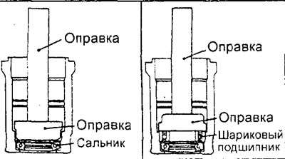
7. Installing the ball bearing.
Lubricate the outer bearing race with working fluid. Using special tools, press the bearing into the valve body.
Recommended fluid - Mitsubishi A TF-SP II
Caution: Do not use ATF-SP I M and ATF-SP III fluid in the steering system.
8. Installing the sealing ring,
a) Knead the sealing ring to soften it.
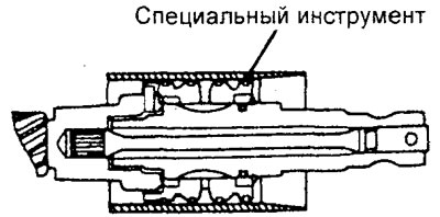
b) Lubricate the sealing ring with the recommended fluid and insert it into the groove of the rack.
Recommended fluid - Mitsubishi ATF-SP II
Caution: Do not use ATF-SP II M and ATF-SP III fluid in the steering system.
c) Insert the conical part of the special tool from the drive gear side and compress the sealing ring.
9. Installing the seal.
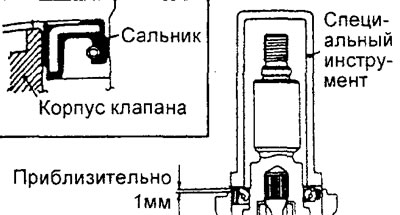
Using a special tool, press the seal into the valve body.
Caution: The top end of the seal must protrude approximately 1 mm above the end of the valve body. Installing the seal flush with or below the end of the valve body may result in fluid leaks and will require reassembly.
11. Installing the plug.
a) Apply the specified sealant to the threads of the plug.
(The material was copied from the website: MitsubishiMan.ru)
Sealant - Three Bond No.1215 or equivalent
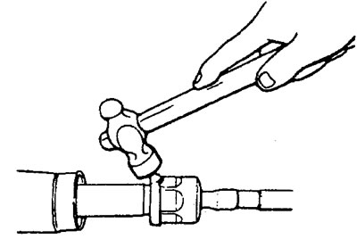
b) After tightening the plug, punch it at two points using a center punch.
12. Installing the rack stop cover and lock nut.
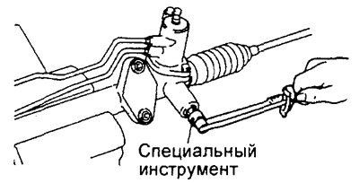
a) Set the rack to its central position. Tighten the rack stop cover to the rated tightening torque using a special tool.
Tightening torque - 15 Nm
b) Unscrew the rack stop cover by approximately 30 degrees.
c) Fix the rack stop cover using a special tool and tighten the lock nut.
13. Adjusting the overall torque of the drive gear.
a) Using a special key, rotate the gear one revolution in 4 - 6 seconds and check the amount of rotation torque and the amount of deviation in rotation torque during the gear rotation.
Nominal value - 0.6 -1.6 Nm
Permissible deviation is 0.4 N·m
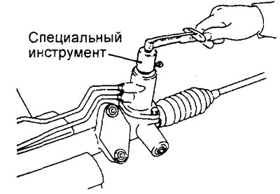
b) If the value of the scrolling moment and the value of the moment deviation do not correspond to the nominal values, then unscrew the rack stop cover by 0 - 30 degrees and adjust the scrolling moment.
Attention:
- During the adjustment process, try to set the upper limit of the nominal value.
- Make sure there are no knocks or jams when moving the steering rack.
- The total torque must be measured throughout the entire stroke of the rack.
Note: If the pinion turning torque cannot be adjusted by turning the rack stop cover to a certain angle, check or replace the rack stop parts and rack stop cover.
c) After completing the adjustment, secure the rack stop cover by tightening the lock nut.
14. Installing the steering rod and lock washer.
After installing the steering rod on the rack, insert the tabs of the lock washer into the grooves of the steering rod in two places.
15 Installing the protective cover tape clamp.
a) Rotate the adjusting bolt of the special tool to adjust the dimension "W" to the nominal value.
Nominal value - W 2.9 mm
Attention:
- If the size is more than 2.9 mm, tighten the bolt.
- If the size is less than 2.9 mm, then unscrew the bolt.
Note:
- One turn of the adjusting bolt changes the "W" dimension by approximately 0.7 mm.
- Do not turn the adjusting bolt more than one turn.
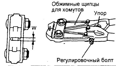
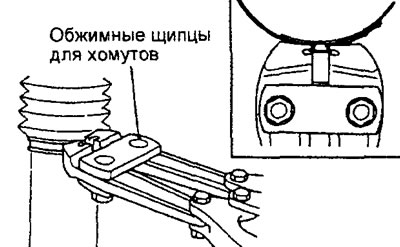
b) Using a special tool, crimp the tape of the protective cover clamp.
Attention:
- Secure the rack body and tighten the band clamp securely.
- Press the band clamp until the tool handle hits the stop.
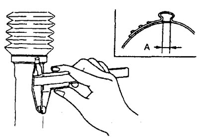
c) Check the clamping width (dimension "A") and its compliance with the nominal value.
Nominal value "A" - 2.4 - 2.8 mm
Attention:
- If the dimension "A" is greater than 2.8 mm, then readjust the dimension "W" as specified in point (a) to the value determined by the specified formula (W = 5.5 mm - A), and repeat the operations of point (b) (for example, if A = 2.9 mm, then W = 2.6 mm).
- If dimension "A" is less than 2.4 mm, remove the band clamp, readjust dimension "W" as specified in point (a) to the value determined by the specified formula (W = 5.5 mm - A), install a new band clamp and repeat points (b) and (c) (for example, if A = 2.3 mm, then W = 3.2 mm).
16. Installing the tie rod end and tie rod end lock nut.
a) Tighten the left and right tie rod ends to the size shown in the figure.
Nominal value "A" - 181 mm
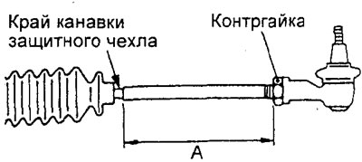
b) Fix the position with a lock nut
Caution: Only tighten the tie rod end locknuts fully after installing the steering gear on the vehicle and adjusting the front wheel alignment.
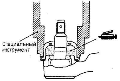
17. Installing the ball joint protective cover.
Note: The protective cover is replaced only if it is damaged during installation.
a) Fill the inner cavity of the protective cover with universal consistent grease.
b) Apply the specified sealant to the sealing edge of the protective cover.
Sealant - Three Bond No.1215 or equivalent
c) Using a special tool, install the protective cover on the ball joint pin of the steering rod end.
d) Hold the ball joint protective boot with your finger and check that it is free from cracks or other damage.
Pre-installation check
1. Check rubber parts for cracks and damage.
2. Check the total torque of the steering gear pinion.
a) To check the total torque of the steering gear pinion, use a special key to rotate the steering gear pinion within one revolution for 4-6 seconds.
Nominal value - 0.6 - 1.6 Nm
Permissible deviation is 0.4 N·m
Note:
- Remove the protective covers from the steering gear housing before checking.
- - Measure the drive pinion torque by turning the drive pinion left and right 180 degrees (full steering rack travel).
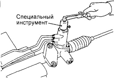
6) If the measured value does not match the standard value, first adjust the position of the steering rack stop cover, and then check the total torque of the steering gear pinion again.
c) If the total torque of the pinion gear cannot be adjusted, check the steering rack stop cover, steering rack stop spring, steering rack stop and replace the parts if necessary.
Caution: When installing the steering gear in a vice, clamp it only at the mounting points. If you clamp the steering gear differently, you can damage or deform the steering gear housing.
3. Check the resistance to rotation of the steering rod joint.
a) Make 10 strong turns of the tie rod end.
b) Using a spring dynamometer, measure the resistance to rotation of the steering rod joint (torque of resistance to rotation).
Nominal value: 6 - 19 N (1.5 - 4.9 Nm)
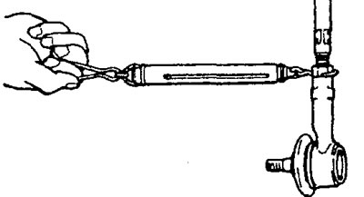
c) If the measured value exceeds the nominal value, replace the steering rod.
d) If the measured value is less than the nominal value, but the steering rod turns smoothly, without excessive play, then such a tip is suitable for use.
4. Check the protective boot of the ball joint of the tie rod end.
a) Hold the ball joint protective boot with your finger and check that it is free from cracks or other damage.
b) If there are cracks or other damage on the protective cover, it must be replaced.
Note:
- Cracks or other damage to the protective cover can lead to damage to the ball joint. Therefore, if the protective cover is damaged during repair, it must be replaced.
Installation
Installation of parts is carried out in the reverse order of removal.
After installing the parts, perform the following operations.
a) Check the protective boot of the ball joint of the tie rod end. Hold the tie rod end with your finger and check that there are no cracks or other damages on it.
b) Fill the power steering system with working fluid.
c) Bleed the power steering hydraulic system.
d) Check the average position of the steering wheel when installing the wheels parallel to the longitudinal axis of the vehicle.
d) Check and, if necessary, adjust the front wheel alignment angles.