
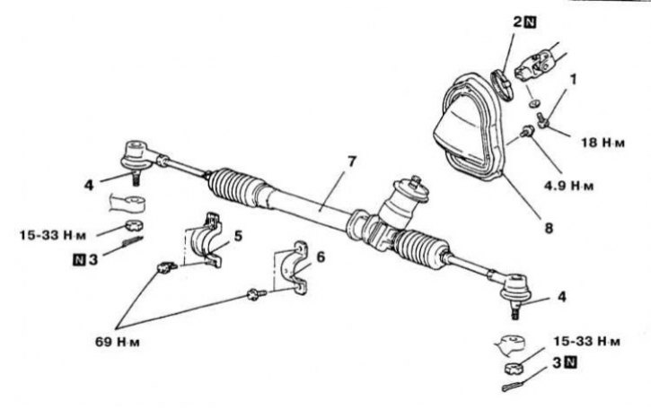
Details of installation of the steering mechanism with a manual drive (Mirage models)
1 - Bolt for fastening the steering column shaft to the axis of the rack and pinion drive gear; 2 - Clamp; 3 - Cotter pin; 4 - Ball pin of the tie rod end; 5 - Mounting clamp; 6 - Mounting clamp; 7 - Carter of the steering mechanism; 8 - Cover; N - Replace
Warning! Some of the car models discussed in this manual are equipped with an additional security system (SRS). Before doing any work near the airbag unit, steering column or instrument panel, turn off the SRS to avoid injury if it is accidentally deployed (see chapter Onboard electrical equipment). SRS circuit wiring is easily identified by the yellow color of the insulation.
Mirage Models
Removing
1. Steering gear installation details on Mirage models are shown in the accompanying illustration.
2. Disconnect the negative cable from the battery.
Attention! If the stereo system installed in the car is equipped with a security code, before disconnecting the battery, make sure that you have the correct combination to activate the audio system!
3. Jack up the car and put it on stands. Remove the front wheels.
4. Disconnect electroconducting from the oxygen gauge and remove a reception pipe of system of release of the fulfilled gases.
5. Support/hang the power package. Give bolts of fastening of both reactive stops of a suspension bracket of the unit.
6. Turn out four fixing bolts and remove a central beam.
7. Release the coupling bolt securing the lower universal joint of the steering column to the input shaft of the rack and pinion, - first mark the installation position of the components.
8. Remove cotter pins, give castellated nuts and release tie rod ends from steering knuckles.
9. Release the fixing bolts of the mounting clamps and remove the steering gear assembly with the rubber pads of its supports through the right wheel arch.
Installation
1. Move the steering mechanism assembly to its regular place, - make sure that the landing marks of the shafts applied during the dismantling are aligned correctly.
2. Install the mounting clamps and tighten the bolts of their fastening with the required force (70 Nm).
3. Torque as required (18 Nm) coupling bolt for fastening the lower shaft of the column to the input shaft of the rack and pinion.
4. Install the center beam.
5. Establish a reception pipe of system of release of the fulfilled gases.
6. Connect the electrical wiring to the oxygen sensor.
7. Connect the tie rod ends to the steering knuckles, tighten the castellated nuts with the required force and fix them with new cotter pins.
8. Check the angles of the front wheels, if necessary, make the appropriate adjustments.