



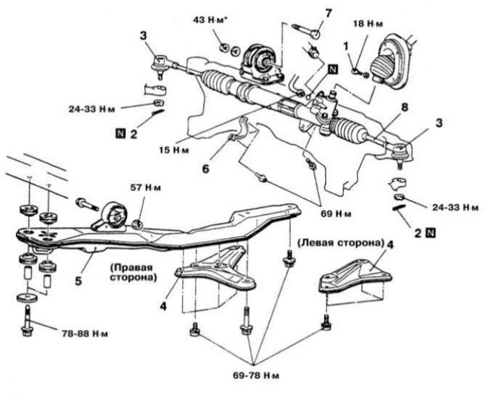
Details of installation of hydraulic power steering on Galant models
1 - Tie bolt securing the lower steering column joint to the rack and pinion input shaft; 2 - Cotter pin; 3 - Tie rod end; 4 - Bracket; 5 - Central beam; 6 - Mounting clamp; 7 - Bolt; 8 - Steering gear; N - Replace
*Final tightening of fasteners marked with an asterisk is carried out after the vehicle has been lowered to the ground.
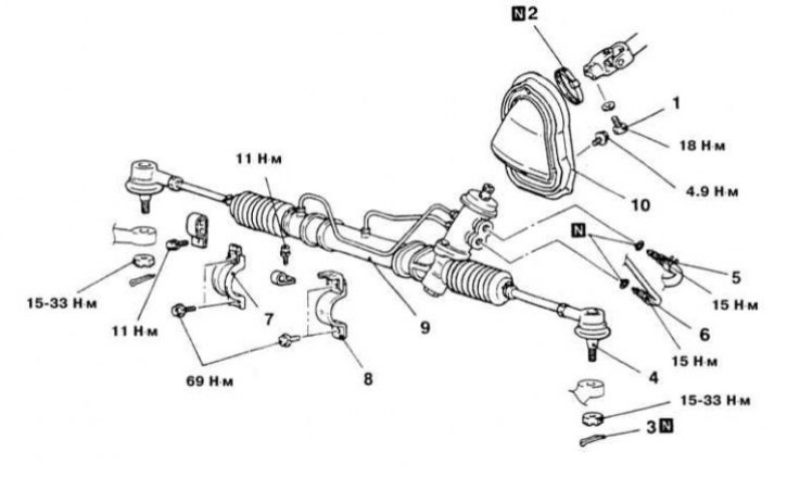
Power steering installation details for Mirage models
1 - Tie bolt securing the lower steering column joint to the rack and pinion input shaft; 2 - Clamp; 3 - Cotter pin; 4 - Tie rod end; 5 - Return pipe; 6 - Pressure tube; 7 - Mounting clamp; 8 - Mounting clamp; 9 - Rack and pinion housing; 10 - Lid; N - Replace
Warning! Some models of vehicles covered in this manual are equipped with a supplemental restraint system (SRS). Before performing any work near the air bag unit, steering column or instrument panel, turn off the SRS to avoid injury from accidental deployment (see Chapter On-board electrical equipment). The SRS circuit wiring is easily identified by the yellow color of the insulation.
Note: Before removing the steering gear, the vehicle's steered wheels should be set to the straight-ahead position, then the steering column should be locked by removing the key from the ignition switch.
Diamante Models
Front wheel steering drive
Removal
1. Disconnect the negative cable from the battery.
Warning! If the car stereo system is equipped with a security code, make sure you have the correct combination to activate the audio system before disconnecting the battery!
2. Drain the power steering fluid.
3. Disconnect the exhaust pipe.
4. On all-wheel drive (AWD) models, remove the transfer case assembly.
5. Unscrew the tie bolt securing the lower hinge of the column shaft to the input shaft of the rack and pinion.
6. Remove the cotter pins, loosen the castle nuts and release the tie rod ends from the steering knuckles.
7. Remove the left and right frame beams.
8. Remove the mounting clamps of the anti-roll bar.
9. On 4WS models, disconnect the hydraulic lines to the rear pump assembly.
10. Unscrew the mounting clamp bolts and remove the steering gear assembly. Remove the assembly from under the vehicle through the right wheel arch.
Installation
1. Place the steering gear assembly in its regular place, screw in the mounting bolts and tighten them with the required force (70 Nm), - make sure that the rubber bushings of the mounting clamps are installed correctly relative to the support beam. Screw in the shaft connection tie bolt.
2. Connect the pressure and return lines to the steering gear housing and, if equipped, to the rear steering pump.
3. Install the frame beams and tighten their mounting bolts with the required force (60÷70 Nm).
4. Connect the tie rod ends to the steering knuckles.
5. On AWD models, install the transfer case assembly.
6. Install the intake pipe of the exhaust system.
7. Add the required amount of hydraulic fluid to the steering reservoir and bleed the steering system.
8. Check the front wheel alignment angles and make appropriate adjustments if necessary.
Rear wheel steering drive
Removal
1. Disconnect the negative cable from the battery.
Warning! If the car stereo system is equipped with a security code, make sure you have the correct combination to activate the audio system before disconnecting the battery!
2. Jack up the car and place it on supports.
3. Drain the power steering hydraulic fluid.
4. Remove the main muffler assembly (see Chapter Power and exhaust systems).
5. Remove the bolts of the lower shock absorber supports.
6. Support the rear differential with a dolly jack. Remove the two small beam support brackets.
7. Loosen the large self-locking nuts securing the beam on the differential side.
8. Unscrew the bolts of the oil line clamps.
9. Remove the pressure line tubes.
10. Hold the tie rod ends from turning and loosen their mounting nuts. Remove the ends from the tie rods.
11. Remove the mounting bolts and remove the rear steering gear assembly.
Installation
1. Secure the steering gear assembly to the frame beam. In order to determine the neutral position of the hydraulic cylinder piston rod, move it to its full stroke length.
2. Insert the ends of the transverse rods into the mounting sockets on the longitudinal suspension arms and screw on the fastening nuts. If necessary, adjust the length of the rods (the difference in the lengths of the opposite rods should not exceed 1 mm), then tighten the nuts to the required force (58 N·m).
3. When replacing the sealing rings, restore the original connection of the hydraulic lines. Ensure that the lines are securely fastened in all intermediate clamps provided.
4. Install the large self-locking nuts securing the frame beam on the differential side. Tighten the nuts to the required torque (110÷130 Nm).
5. Remove the jack supporting the differential.
6. Install two small brackets.
7. Install the lower shock absorber mount bolts.
8. Install the main muffler.
9. Fill the hydraulic system reservoir with the required amount of fluid and bleed the system.
10. Check the wheel alignment angles. Make the appropriate adjustments if necessary.
Galant Models
Models up to 1993 release.
Removal
1. Disconnect the negative cable from the battery.
Warning! If the car stereo system is equipped with a security code, make sure you have the correct combination to activate the audio system before disconnecting the battery!
2. Disconnect the exhaust pipe.
3. Drain the power steering fluid.
4. Unscrew the tie bolt securing the lower hinge of the column shaft to the input shaft of the rack and pinion transmission.
5. If equipped, remove the transfer case.
6. Remove the cotter pins, loosen the castle nuts and release the tie rod ends from the steering knuckles.
7. Locate the triangular brackets (knicknames) near the mounting clamps that secure the anti-roll bar to the frame beam. Remove both the knicknames and the mounting clamps.
8. Support the center beam.
9. Remove the through bolt from the round torque strut of the powertrain mount.
10. Remove the rear bolts of the center beam.
11. On front-wheel drive (FWD) models, disconnect the exhaust downpipe.
12. Disconnect the pressure line and return hose from the steering gear housing - to minimize leaks and to prevent dirt from entering the hydraulic system, immediately seal the open ends of the lines and connecting nipples.
13. Lower the center beam slightly.
14. Unscrew the mounting clamp bolts and remove the steering gear assembly. Remove the assembly from under the car through the left wheel arch, first moving it to the right and tilting it to remove it from the beam.
Installation
1. Install the steering gear assembly in its regular place. Screw in the mounting bolts and tighten them to the required torque (60÷80 Nm). When installing the rubber support pads, make sure that their projections are correctly aligned with the identification marking on the beam.
2. Connect the hydraulic lines to the steering gear housing.
3. Reinstall the removed sections of the exhaust system.
4. Support the central beam with a jack, screw in the mounting bolts and tighten them to the required torque (100 Nm).
5. Install the reaction stop bolt, screw a new nut onto it and tighten it to the required torque (65 Nm).
6. Install the anti-roll bar fastening elements.
7. Connect the steering rods and tighten the fastening nuts of their ends to the required torque (34 N·m).
8. If equipped, install the transfer case - check the fluid level in its crankcase.
9. Fill the steering pump reservoir with the required amount of hydraulic fluid of the required grade (see Chapter Settings and ongoing maintenance).
10. Bleed the power steering system.
11. Check the front wheel alignment angles and make appropriate adjustments if necessary.
Models since 1994.
Removal
1. Steering gear installation details on Galant models are shown in the illustration.
2. Disconnect the negative cable from the battery.
Warning! If the car stereo system is equipped with a security code, make sure you have the correct combination to activate the audio system before disconnecting the battery!
3. Jack up the car and place it on supports.
4. Remove the front wheels.
5. Unscrew the tightening bolt securing the lower steering column joint to the input shaft of the rack and pinion transmission.
6. Remove the anti-roll bar.
7. Remove the cotter pins, loosen the nuts and, using a special puller type MB991113, release the steering rod ends from the steering knuckle assemblies.
8. On models with electronic power steering (EPS) control, disconnect the wiring harness from the solenoid connector.
9. Remove the two triangular brackets located near the central beam.
10. Support the center beam with a jack. Remove the through bolt from the front torque strut, then unscrew the beam mounting bolts.
11. Remove the center beam.
12. Support the power unit with a trolley jack and remove the through bolt of the rear torque support.
13. Disconnect the pressure line and the return hose of the power steering hydraulic circuit from the rack and pinion housing - immediately plug the open ends of the lines and fittings.
14. Remove the mounting bolts and remove the steering gear assembly through the left wheel arch.
Installation
1. Place the steering gear assembly in its original position and connect the steering column shaft to the input shaft of the rack and pinion.
2. Screw in the mounting bolts and tighten them to the required torque (69 Nm).
3. Screw in the tie bolt and tighten it to the required torque (18 Nm).
4. Connect the hydraulic lines to the steering gear housing. Tighten the pressure line nipple with a torque of 43 N·m. Make sure that the clamp on the nipple is securely fastened with the return hose.
5. Screw in and tighten to the required torque (43 Nm) the through bolt of the rear reaction stop.
6. Support the central beam with a jack. Screw in the central mounting bolts. Tighten the front bolts with a force of 78÷88 N·m, the rear ones - 69÷78 N·m.
7. Screw in the through bolt of the front reaction stop and tighten it to the required torque (43 N·m).
8. Install two triangular brackets and tighten their mounting bolts to the required force (69÷78 Nm).
9. Install the anti-roll bar.
10. Connect the steering rods to the steering knuckles, tighten the ball joint nuts with the required torque (27 Nm).
11. On models equipped with EPS, reconnect the appropriate electrical wiring.
12. Replace the wheels and lower the car to the ground. Connect the negative cable to the battery.
13. Add the required amount of hydraulic fluid of the required grade to the steering pump reservoir (see Chapter Settings and ongoing maintenance) and bleed the power steering system.
14. Check the front wheel alignment angles and make appropriate adjustments if necessary.
Mirage Models
Models up to 1992 release.
Removal
1. Disconnect the negative cable from the battery.
Warning! If the car stereo system is equipped with a security code, make sure you have the correct combination to activate the audio system before disconnecting the battery!
2. Jack up the car and place it on supports.
3. Remove the front wheels.
4. Unscrew the tightening bolt securing the lower steering column joint to the input shaft of the rack and pinion transmission.
5. Remove the cotter pins, loosen the nuts and release the tie rod ends from the steering knuckle assemblies.
6. Remove the anti-roll bar.
7. Disconnect the pressure line and the return hose of the power steering hydraulic circuit from the rack and pinion housing - immediately plug the open ends of the lines and fittings.
8. Remove the mounting bolts and remove the steering gear assembly through the left wheel arch.
Installation
1. Place the steering gear assembly in its regular place and connect the steering column shaft to the input shaft of the rack and pinion. Make sure the fasteners are tightened securely.
2. Connect the hydraulic lines to the steering gear housing.
3. Reinstall the stabilizer bar and rear transmission mount bracket.
4. Connect the steering rods to the steering knuckles.
5. Replace the wheels and lower the car to the ground. Connect the negative cable to the battery.
6. Add the required amount of hydraulic fluid of the required grade to the steering pump reservoir (see Chapter Settings and ongoing maintenance) and bleed the power steering system.
7. Check the front wheel alignment angles and make appropriate adjustments if necessary.
Models since 1993.
Removal
1. Steering gear installation details on Mirage models are shown in the illustration.
2. Drain the working fluid from the power steering system.
3. Disconnect the negative cable from the battery.
Warning! If the car stereo system is equipped with a security code, make sure you have the correct combination to activate the audio system before disconnecting the battery!
4. Jack up the car and place it on supports.
5. Remove the front wheels.
6. Disconnect the electrical wiring from the oxygen sensor and remove the exhaust pipe.
7. Support the engine.
8. Remove the bolts of both reaction stops.
9. Loosen the mounting bolts and remove the center beam.
10. Mark the position of the rack and pinion input shaft relative to the lower steering column joint. Remove the pinch bolt and disconnect the joint.
11. Remove the cotter pins, loosen the nuts and release the tie rod ends from the steering knuckle assemblies.
12. Disconnect the pressure line and the return hose of the power steering hydraulic circuit from the rack and pinion housing - immediately plug the open ends of the lines and fittings.
13. Remove the mounting bolts and remove the steering gear assembly through the right wheel arch.
Installation
1. Place the steering gear assembly in its regular place and connect the steering column shaft to the input shaft of the rack and pinion transmission - ensure that the alignment marks applied during dismantling are correctly aligned.
2. Screw in the mounting bolts and tighten them to the required torque (70 Nm).
3. Screw in the tie bolt and tighten it to the required torque (18 Nm).
4. Connect the hydraulic lines to the steering gear housing - do not forget to replace the sealing rings.
5. Install the center beam.
6. Install the intake pipe of the exhaust system.
7. Connect the electrical wiring to the oxygen sensor.
8. Connect the steering rods to the steering knuckles, tighten the ball joint nuts with the required force (25 Nm).
9. Replace the wheels and lower the car to the ground. Connect the negative cable to the battery.
10. Add the required amount of hydraulic fluid of the required grade to the steering pump reservoir (see Chapter Settings and ongoing maintenance) and bleed the power steering system.
11. Check the front wheel alignment angles and make appropriate adjustments if necessary.