



Contents: Removal and installation ⤓ Checking the heater electric fan…⤓ Switch test table. ⤓ Disassembly and assembly ⤓
Removal and installation
− The parts are removed in the order of numbers shown in the figure "Removing the air conditioner control panel assembly".
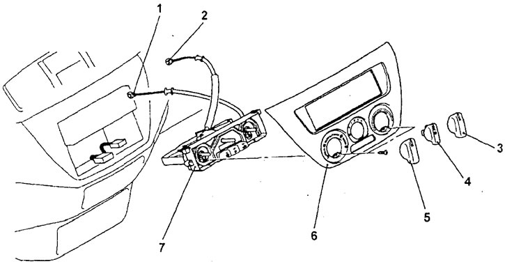
Removal the control panel assembly (air conditioner with manual control). 1 - air flow mixing flap drive cable, 2 - air flow direction selection flap drive cable, 3 - temperature regulator switch, 4 - heater electric fan speed switch, 5 - air flow distribution mode selection switch, 6 - heater and air conditioner control panel trim, 7 - manual air conditioner control panel assembly.
− Installation of parts is carried out in the reverse order of removal.
Note: After connecting the cables, make sure the flaps move freely.
- When installing parts, pay attention to the following operations:
1. Connecting the air flow direction selector flap drive cable.
a) Set the air flow direction selector knob to the "DEF" (windshield heating) position.
b) Set the air flow direction selector flap lever on the heater unit to the "DEF" position as shown in the figure, then connect the cable to the lever.
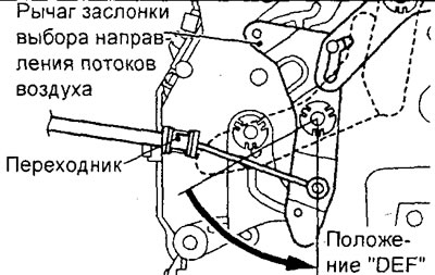
c) Install the adapter on the heater body and secure it with the clamp.
2. Connecting the air flow mixing flap drive cable.
a) Set the air temperature control knob on the heater control panel to the "MAX HOT" position (maximum heating).
b) Set the air flow mixing flap lever on the heater unit to the "MAX HOT" position, as shown in the figure, then connect the cable to the lever.
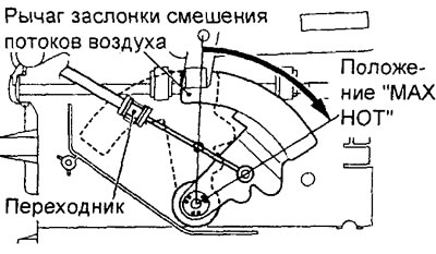
c) Install the adapter on the heater body and secure it with the clamp.
Checking the heater electric fan switch
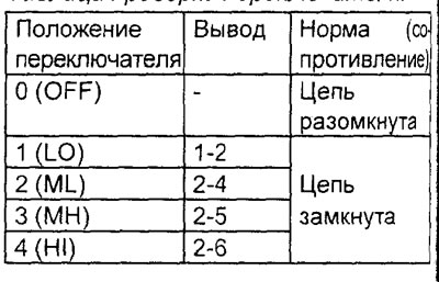
Check the condition of the circuit between the connector terminals at different switch positions according to the table below.
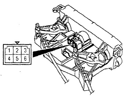
Switch test table.
Disassembly and assembly
− The parts are removed in the order of the numbers shown in the figure "Disassembling the air conditioner control panel".
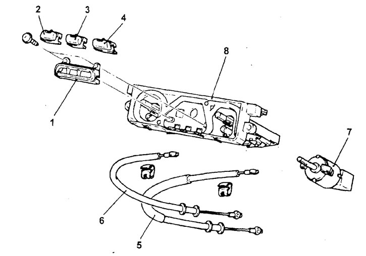
Disassembling the air conditioner control panel (air conditioner with manual control). 1 - switch panel, 2 - rear window heater switch, 3 - air conditioner switch, 4 - air intake mode selection switch, 5 - air flow direction selection flap drive cable, 6 - air flow mixing flap drive cable, 7 - heater electric fan speed switch assembly, 8 - air conditioner control panel (compressor electronic control unit).
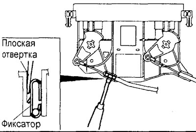
- When removing parts, pay attention to the operations for removing the damper cables.
Insert a flat-head screwdriver into the control panel from the inside, then pull out the cable by pressing the lock as shown in the figure.
− Installation of parts is carried out in the reverse order of removal.