Contents: Air conditioning system refill ⤓ Refilling the air conditioning…⤓ Pumping out refrigerant from the air…⤓ Filling the air conditioning system…⤓ Checking the efficiency of the air…⤓ Checking the electronic control unit…⤓ Checking the electronic control unit…⤓ Elimination of leaks ⤓ Adjustment ⤓ Table. Checking the voltage at the…⤓ Table for checking the voltage at…⤓
Air conditioning system refill
1. With the valve handles turned all the way out (valves closed), install the transition valve to the low pressure fitting of the measuring manifold.
2. Connect the filling hose (blue) to the adapter valve.
3. Connect the quick release coupling (low pressure lines) to the filling hose (blue).
Attention:
- Use only special equipment and tools suitable for R-134a refrigerant.
- To install the quick coupling, press the "A" part of the coupling firmly towards the service valve until it clicks. When connecting the quick coupling, press the coupling and run your hand along the hose to ensure there are no kinks.
4. Connect the quick release coupling (low pressure lines) with hose to the low pressure service valve of the air conditioning system.
Note: The low pressure service valve must be connected to the low pressure hose (leading to the compressor).
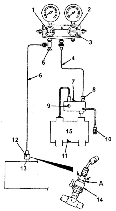
1 - Low pressure valve, 2 - High pressure valve, 3 - Measuring manifold, 4 - Charging hose (yellow), 5 - Adapter valve, 6 - Charging hose (blue), 7 - Switch, 8 - Fitting (R-134a), 9 - Vacuum pump adapter, 10 - Power plug, 11 - Switch, 12 - Quick release coupling (for low pressure line), 13 - Low pressure service valve, 14 - Coupling, 15 - Vacuum pump.
5. Close the high and low pressure valves on the measuring km meter.
6. Connect the vacuum pump adapter to the vacuum pump.
7. Connect the type and power cord to the adapter.
8. Connect the charging hose (yellow) to the "R-134a" fitting on the vacuum pump adapter.
9. Tighten the adapter valve handle (valve open).
10. Open the low pressure valve of the measuring manifold.
11. Set the vacuum pump switch to the "ON" position.
Note: Even if the vacuum pump switch is in the "ON" position, the vacuum pump will continue to operate until the power supply is connected (see item "7").
12. To start the vacuum pump, return the switch of the vacuum pump adapter to the "R-134a" nipple.
Caution: Do not use a compressor to recover refrigerant.
13. Pump down to a vacuum of 100 kPa or higher (the process takes about 10 minutes).
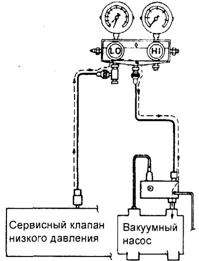
14. Set the vacuum pump adapter switch to the "OFF" position and wait for 5 minutes. Caution: Do not operate the air conditioning compressor if there is a leak in the system. Otherwise, it may be damaged.
15. Check the system for leaks (the system is in good condition if the vacuum does not decrease).
Caution: If the vacuum drops, tighten all connections more firmly and then repeat the pumping procedure, starting from point "12".
16. Unscrew the adapter valve handle (the valve is closed), remove it from the measuring manifold and install the filling cylinder.
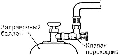
17. To fill the system with refrigerant, unscrew the handle of the filling valve (valve open) and screw in the handle of the adapter valve (valve open).
Caution: If the filling cylinder is upside down, liquid refrigerant may enter the compressor and cause damage. Always install the cylinder in an upright position to ensure that the refrigerant is charged in a gaseous state.
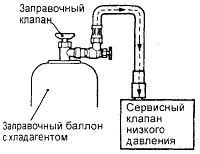
18. If the refrigerant does not enter the system, then unscrew the adapter valve handle (the valve is closed).
19. Using a leak detector, check the air conditioning system for leaks. If refrigerant leaks are detected, retighten all connections and repeat the charging procedure, starting with the refrigerant recovery operation in step "12".
Caution: To check the system for leaks, it is necessary to use a special leak detector for R-134a refrigerant.
20. Start the engine.
21. Turn on the air conditioner and set the temperature control switch to the "MAX COOL" position.
22. Maintain the engine operating mode at 1500 rpm.
23. To fill the required volume of refrigerant, tighten the adapter valve handle (the valve is open).
Attention: do not allow the filling cylinder to turn over, as this may cause liquid refrigerant to enter the compressor and damage it. Only installing the cylinder in a vertical position (valve at the top) will ensure that the system is filled with refrigerant in a gaseous state.
24. After filling the system with refrigerant, unscrew the adapter valve handle until it stops (the valve is closed).
25. Turn the filling valve handle all the way (valve closed).
26. Disconnect the quick release coupling (low pressure lines) from the low pressure service valve.
Note: If there is some refrigerant left in the filling cylinder, leave the filling valve and adapter valve handles closed until the next filling.
Refilling the air conditioning system in case of low refrigerant level
1. Unscrew the adapter valve handle until it stops (valve closed) and insert it into the filling valve.
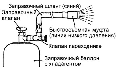
2. Connect the filling hose (blue) to the adapter valve.
3. Connect the quick-release coupling (low pressure lines) to the filling hose (blue).
4. Turn the handle of the filling valve all the way (valve closed) to pierce a hole in the cylinder. Turn the handle of the filling valve all the way (valve open).
5. Turn the adapter valve handle and remove air.
6. Connect the quick release coupling (low pressure lines) to the low pressure service valve.
Note: The service valve must be connected to the low pressure hose.
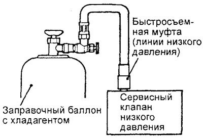
7. Start the engine.
8. Turn on the air conditioner and set the temperature control switch to the "MAX COOL" position.
9. Maintain the engine operating mode at 1500 rpm.
10. Tighten the adapter valve handle (valve open) and fill the system with the required amount of refrigerant. Monitor the filling process using the sight glass.
Caution: Do not allow the filling cylinder to turn upside down, as this may cause liquid refrigerant to enter the compressor and damage it. Only installing the cylinder in a vertical position (valve on top) will ensure that the system is filled with refrigerant in a gaseous state.
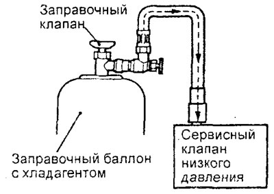
11. After completing the refrigerant refill, unscrew the adapter handle as far as it will go (the valve is closed) and remove the quick-release coupling.
Note: If there is any refrigerant left in the filling cylinder, close the filling valve and adapter valve completely, then store the cylinder until the next filling.
Pumping out refrigerant from the air conditioning system
Note: This procedure is performed in the absence of a special device for refrigerant disposal.
1. Start the engine and let it run for 5 minutes at 1200-1500 rpm with the air conditioner running to evenly distribute the compressor oil throughout the system.
Note: Compressor oil circulation through the air conditioning system is more efficient if it is done while the vehicle is moving.
2. Turn off the engine.
3. Unscrew the adapter valve handle as far as it will go (the valve is closed) and connect the filling hose (blue) to it.
4. Connect the quick release coupling to the filling hose (blue).
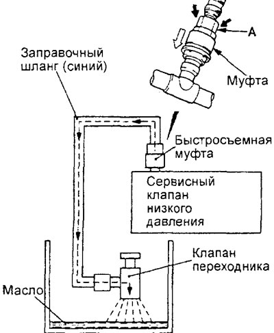
5. Connect the quick release coupling to the system's low pressure service valve.
Note: The low pressure service valve must be connected to the low pressure hose (leading to the compressor).
Attention:
- - To install the quick-release coupling, press the coupling part "A" firmly towards the service valve until it clicks.
- - When connecting the quick release coupling, press the coupling and run your hand along the hose to ensure there are no kinks.
6. Install the adapter valve inside the drain tank and gradually release the refrigerant from the air conditioning system by smoothly opening the valve to prevent compressor oil from splashing.
Note: Any remaining compressor oil in the drain tank should be returned to the air conditioning system when recharging with refrigerant.
Filling the air conditioning system with compressor oil
1. Insufficient amount of compressor oil in the air conditioning system will not provide the necessary lubrication of the compressor, which will lead to its failure. Excess oil in the system will lead to an increase in the temperature of the cooled air.
2. When installing the compressor at the manufacturer"s plant, 140±10 ml of special compressor oil is poured into it.
Compressor oil - SUN PAG 56
3. When the air conditioner is operating, the oil is distributed along with the refrigerant throughout all the elements of the system, and a certain amount of oil remains in various parts of the system. When replacing one part of the air conditioning system (evaporator, condenser, receiver-dryer, compressor hoses), you should add to it the amount of oil that was removed with the removed part (in order to maintain the oil balance in the system).
Checking the efficiency of the air conditioner
1. The vehicle being tested should not be exposed to direct sunlight. The outside air temperature should be 16-30°C with humidity of 60-100%.
2. Close the low and high pressure valves on the measuring manifold.
3. Connect the filling hose (blue) to the low pressure valve of the manifold and the filling hose (red) to the high pressure valve.
4. Install the quick-release coupling (for low pressure) on the filling hose (blue) and the quick-release coupling (for high pressure) on the filling hose (red).
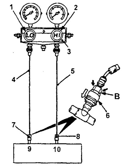
1 - low pressure valve, 2 - high pressure valve, 3 - measuring manifold, 4 - filling hose (blue), 5 - filling hose (red), 6 - coupling, 7 - adapter valve (for low pressure line), 8 - adapter valve (for high pressure line), 9 - low pressure service valve, 10 - high pressure service valve.
5. Connect the appropriate quick-release couplings to the low and high pressure service valves of the system.
Note: The high pressure service valve is located on the high pressure pipe (from the compressor) and the low pressure service valve is located on the low pressure hose (from the compressor).
Attention:
- - To install the quick-release coupling, press the "B" part of the coupling firmly towards the service valve until it clicks.
- - When connecting the quick release coupling, press the coupling and run your hand along the hose to ensure there are no kinks.
6. Start the engine.
7. Set the air conditioner to the following operating mode:
- Air conditioner switch: "ON" position;
- Air supply mode selection lever: "FACE" (to the head area);
- Temperature controller switch: "MAX COOL" (maximum cooling);
- Air intake mode selection lever: "RECIRC" (recirculation);
- Heater electric fan switch: position "4" (high speed).
8. Maintain the engine operating mode at 1500 rpm with the air conditioner on (the compressor electromagnetic clutch engaged).
9. Make sure the pressure in the high pressure line is in the range of 1667 - 1765 kPa.
Note: If the pressure is greater than the specified, cool the condenser; if the pressure is less than the specified, cover the condenser.
10. Warm up the engine with the doors and windows closed, the car hood should be open.
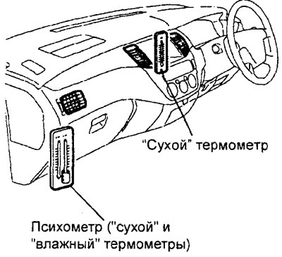
11. Install the thermometer and psychrometer as shown in the figure and let the engine run for 20 minutes.
Attention:
- - Set the dry thermometer so that it shows the temperature of the air coming out of the deflector.
- - Install the psychrometer so that it does not interact directly with the air coming out of the deflectors.
11. Record the temperature of the air entering the cabin.
Note: If the compressor electromagnetic clutch is in ON/OFF mode, record the temperature before it turns off.
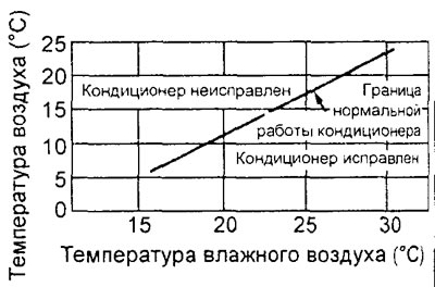
12. Check the operation of the air conditioner according to the schedule.
Checking the electronic control unit of the engine and variator
Disconnect the connector from the electronic engine and CVT control unit and check the connector on the wiring harness side according to the table "Checking the voltage at the terminals of the electronic engine and CVT control unit".
Checking the electronic control unit of the compressor (built into the air conditioner control panel)
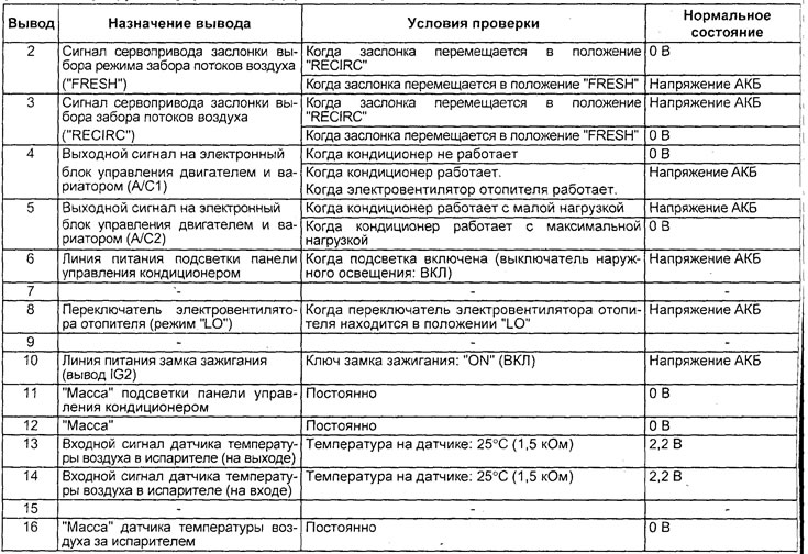
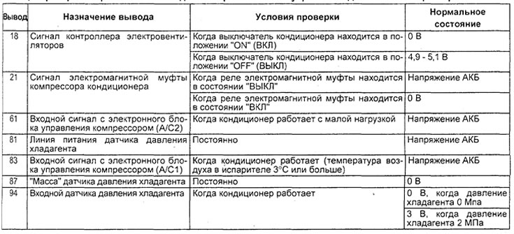
Disconnect the connector from the compressor electronic control unit and check the connector on the wiring harness side according to the table "Checking the voltage at the terminals of the compressor electronic control unit".
Caution: To avoid damaging the servo drive, the duration of the voltage test at the corresponding terminals should not exceed 40 seconds.
Elimination of leaks
Complete loss of refrigerant
If there is no refrigerant left in the system due to a leak, perform the following operations:
- 1. Evacuate the refrigerant from the system (see the appropriate procedure).
- 2. Charge approximately 0.550 kg of refrigerant into the system.
- 3. Check the system for refrigerant leaks.
- 4. Pump the refrigerant out of the system.
- 5. Repair any leaks found.
- 6. Replace the receiver-drier.
Attention: when storing the receiver-dryer, it must be hermetically sealed and closed. The desiccant used in the receiver-dryer unit is very quickly saturated with water vapor from the atmosphere when opened. In this regard, replace the receiver-dryer as quickly as possible, having prepared all the necessary tools and accessories in advance, so that the open receiver-dryer is exposed to the air as little as possible.
- 7. Evacuate the refrigerant from the system and then completely charge the air conditioning system with refrigerant.
Insufficient amount of refrigerant in the system
In case of partial refrigerant leakage, locate the leaks and eliminate them. If it is necessary to increase the pressure in the system to locate the leak (due to insufficient refrigerant in the system), then top up the system.
If it is possible to repair the leaks without completely removing the refrigerant from the system, use the "Recharging the A/C System When the Refrigerant Level Is Low" procedure.
Eliminating Compressor Noise
1. Find out the conditions under which the noise occurs. These include: weather conditions, vehicle speed, whether the transmission is in gear or neutral, engine temperature, or other specific conditions.
2. Noises that occur when the air conditioner is running can often be misleading. For example, noise similar to the sound of a faulty front bearing or a connecting rod knock can be caused by loose bolts, nuts, brackets, or loosening (increased wear) of the air conditioner compressor clutch.
3. Also check the tension of the alternator and power steering pump drive belts.
4. Incorrectly adjusted tension of the drive belts of the attachments can cause noise that is mistaken for the noise created by the compressor during operation. This noise disappears when the compressor is turned off.
5. The noise from the drive belts depends on their rotation speed. Therefore, depending on the belt tension, at different engine speeds, the drive belts can produce extraneous noises, which are often mistaken for the sounds of a faulty compressor.
Adjustment
1. Select a quiet area to conduct the test. If possible, repeat the conditions of the extraneous noise as completely as possible. To clearly distinguish the sound of the compressor, turn it on and off several times.
Note: To simulate high altitude conditions, limit the air flow through the condenser. Install a pressure gauge assembly to monitor the discharge pressure, which should not exceed 2070 kPa.
2. Tighten all compressor mounting bolts, the air conditioner compressor clutch mounting bolt and adjust the compressor drive belt tension. Check the reliability of the compressor electromagnetic clutch winding installation (no rotation or wobble).
3. Check that the air conditioning system hoses do not touch or rub against adjacent parts, which may cause extraneous noise.
4. Check the refrigerant level.
5. Listen again to the sound of the compressor operating as described in point "1".
6. If the extraneous noise does not disappear, loosen the compressor mounting bolts and tighten them again. Repeat the check according to point "1".
7. If the extraneous noise remains, replace the compressor and then repeat the check according to point "1".

Connector of the electronic control unit of the engine and variator.
Table. Checking the voltage at the terminals of the electronic control unit of the engine and variator.
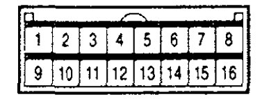
Compressor electronic control unit connector (manual air conditioner).
Table for checking the voltage at the terminals of the electronic compressor control unit (air conditioner with manual control).