Contents: Removal and installation ⤓ Disassembly and assembly of the…⤓ Checking the dual switch for coolant…⤓
Removal and installation
Note: Checking the compressor electromagnetic clutch is provided in the section "Basic checks".
- Before removing parts, pump out the refrigerant from the air conditioning system.
− The parts are removed in the order of numbers indicated in the figure "Removing the compressor and the drive belt of the attachments".
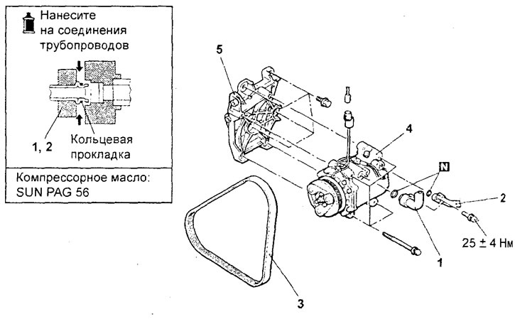
Removal the compressor and the drive belt of the attachments. 1 - low pressure hose connection (supply to compressor), 2 - high pressure hose connection (discharge), 3 - drive belt for attachments, 4 - compressor, 5 - compressor mounting bracket.
- When removing parts, pay attention to the following operations:
1. Disconnect the low pressure hose and high pressure hose.
Close the disconnected compressor hoses and fittings to prevent moisture, dust and other contaminants from entering.
Caution: Hoses must be hermetically sealed, otherwise the compressor oil and receiver-dryer may become saturated with water vapor from the atmosphere. Do not use porous material to close tubes and fittings.
The original can be found on the website mitsubishiman.ru
2. Removing the compressor drive belt.
For removal of the compressor drive belt, see chapter "Engine - Mechanical part".
3. Removing the compressor.
Caution: Be careful when removing the compressor to avoid leakage of compressor oil.
− Installation of parts is carried out in the reverse order of removal.
- When installing the parts, pay attention to the compressor installation operation.
If a new compressor is installed, first adjust the oil volume as described below, and then install the compressor (i.e. maintain the oil balance in the air conditioning system).
a) Measure the amount of oil [X ml] that was in the removed compressor.
b) Drain the amount of oil [Y ml] from the new compressor calculated using the formula below, and then install the new compressor in place.
The volume of oil in a new compressor is 140 ml - X ml = Y ml
Note: [Y ml] refers to the amount of oil remaining in the pipes, condenser, evaporator, hoses, etc.
- After completing the installation of the parts, perform the following operations:
- a) Fill the air conditioning system with refrigerant.
- b) Adjust the tension of the compressor drive belt.
Disassembly and assembly of the electromagnetic clutch of the compressor
The parts are removed in the order of numbers indicated in the figure "Disassembling the compressor electromagnetic clutch".
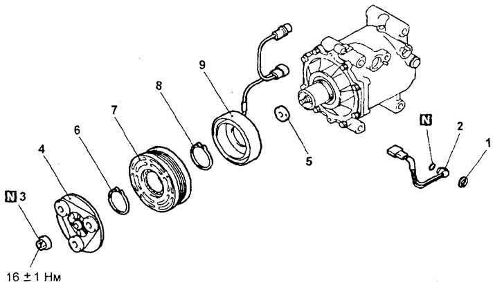
Disassembling the compressor electromagnetic clutch. 1 - retaining ring, 2 - coolant temperature switch (check the air gap in the electromagnetic clutch during installation), 3 - self-locking nut, 4 - armature disk, 5 - washer, 6 - retaining ring, 7 - rotor, 8 - retaining ring, 9 - clutch winding.
- When removing parts, pay attention to the operation of loosening the self-locking nut of the compressor pulley.
Installation of parts is carried out in the reverse order of removal.
- When installing the parts, pay attention to the following operations.
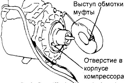
1. Installation of the electromagnetic clutch winding.
When installing the coupling winding onto the compressor housing, align the protrusion of the coupling winding with the hole in the compressor housing.
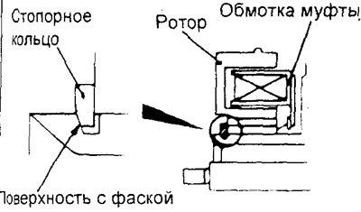
2. Installing the retaining ring.
Install the retaining ring so that the chamfered end is on the outside as shown in the figure.
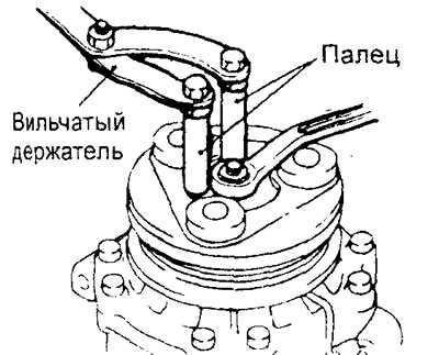
3. Installing the compressor pulley self-locking nut.
Using a special tool, secure the electromagnetic clutch and tighten the compressor pulley nut.
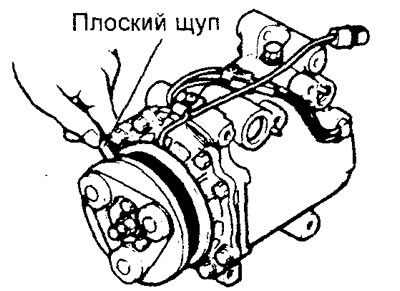
4. Checking the air gap in the electromagnetic clutch.
Check whether the air gap in the electromagnetic clutch corresponds to the nominal value.
Nominal value - 0.3 - 0.5 mm
Note: If the measured gap does not correspond to the nominal value, make the necessary gap adjustment by changing the number of adjusting washers.
Checking the dual switch for coolant temperature
1. Immerse the measuring part of the switch in oil. Then heat the oil with a gas burner or similar device.
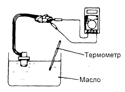
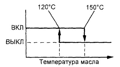
b) When the oil temperature reaches the specified value, check that the circuit is open between the terminals of the sensor switch.
Nominal value:
- OFF-ON - 150°C
- ON-OFF - 120°C