



Contents: Reading and clearing fault codes ⤓ Checking the electronic control unit…⤓ Table. Air conditioning system fault…⤓ Table. Checking the voltage at the…⤓ Checking system components ⤓ Disassembly and assembly of the…⤓ Removal and installation the heater…⤓ Removal and installation the…⤓ Removal and installation of servo…⤓ Removal and installation sensors ⤓
Reading and clearing fault codes
Reading and deleting fault codes for the air conditioning system is only possible using a tester.
The procedure for reading codes using a tester is given in the chapter "Fuel injection system (MPI)".
Note: The description of the fault codes is given in the table "Fault codes of the air conditioning system"
Checking the electronic control unit of the air conditioner
(Original material on the website: www.mitsubishiman.ru)
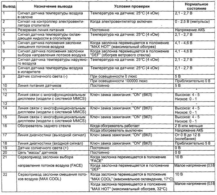
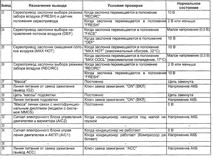
Disconnect the connector from the air conditioning control unit and check the connector on the wire harness side according to the table "Checking the voltage at the terminals of the air conditioning control unit".
Caution: To avoid damaging the servo, the test duration should not exceed 40 seconds.
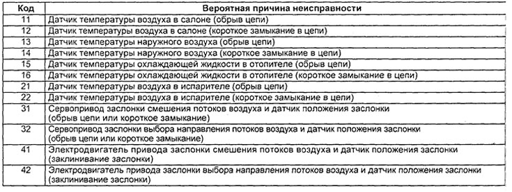
Table. Air conditioning system fault codes.

Air conditioning electronic control unit connectors.
Table. Checking the voltage at the terminals of the air conditioner electronic control unit.
Checking system components
1. Checking the air flow mixing flap servo drive.
Apply power (battery voltage) to terminals "1" (-) and "3" (+) of the electric motor connector and check that the air intake mode selection flap lever moves toward the "MAX. COOL" position. Also check that the air intake mode selection flap lever moves in the opposite direction (toward the "MAX. HOT" position) when changing the polarity of the power connection.
Caution: Turn off the power when the damper is in the "MAX. COOL" or "MAX. HOT" position.
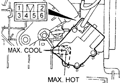
2. Checking the air flow mixing flap servo position sensor.
Connect the tester between terminals "2" and "5" and between terminals "5" and "6" and check that the resistance changes gradually when the throttle is moved to the "MAX. COOL" or "MAX. HOT" position.
Nominal value - 0.65 - 5.35 kOhm
3. Checking the servo drive of the air flow direction selection flap.
Apply power (battery voltage) to terminals "1"(+) and "3"(-) of the electric motor connector and check that the air intake mode selector lever moves toward the "DEF" position. Also check that the air intake mode selector lever moves in the opposite direction (toward the "FACE" position) when the polarity of the power connection is changed.
Caution: Turn off the power after the throttle moves to the "DEF" or "FACE" position.
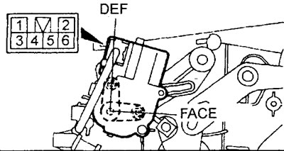
4. Checking the position sensor of the air flow direction selector flap servo drive.
Connect the tester between terminals "2" and "5" and between terminals "5" and "6" and check that the resistance changes gradually when the throttle is moved to the "DEF" or "FACE" position.
Nominal values - 0.65 - 5.35 kOhm
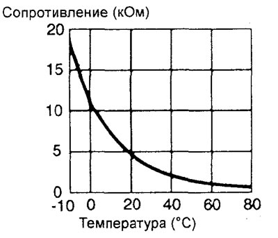
5. Checking the coolant temperature sensor in the evaporator.
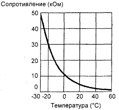
Measure the resistance between the sensor terminals for two or more temperature values. The resistance between the sensor terminals should differ slightly from the value indicated on the graph.
Note: When checking, the air temperature should not go beyond the range in which the curve is located on the graph.
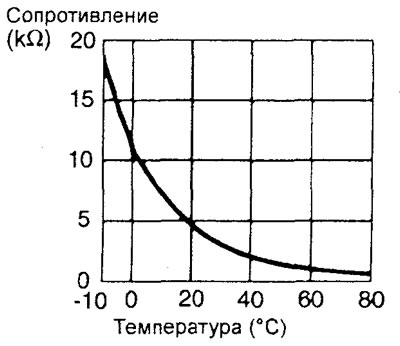
6. Checking the cabin air temperature sensor.
Measure the resistance between the sensor terminals for two or more temperature values. The resistance between the sensor terminals should differ slightly from the value shown on the graph.
Note: When checking, the air temperature should not go beyond the range in which the curve is located on the graph.
7. Checking the Sunlight Sensor. If the speed of the heater fan decreases when the sensitive side of the sunlight sensor is covered with a hand and the air conditioner is operating in the "AUTO" mode, the sunlight sensor is OK. If the speed of the heater fan does not change, replace the sunlight sensor.
8. Checking the air temperature sensor in the evaporator.
Measure the resistance between the sensor terminals for two or more temperature values. The resistance between the sensor terminals should differ slightly from the value indicated on the graph.
Note: When checking, the air temperature should not go beyond the range in which the curve is located on the graph.
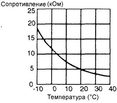
9. Checking the outside air temperature sensor.
Measure the resistance between the sensor terminals for two or more temperature values. The resistance between the sensor terminals should differ slightly from the value indicated on the graph.
Note: When checking, the air temperature should not go beyond the range in which the curve is located on the graph.
Disassembly and assembly of the heater unit
Disassembly of parts is carried out in the order of numbers indicated in the figure "Disassembly of the heater unit".
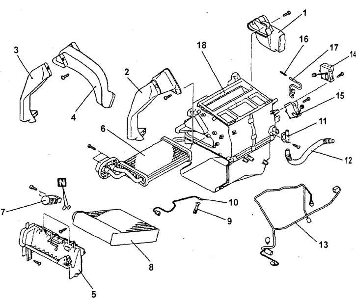
Disassembling the heating unit (air conditioning with automatic control). 1 - footwell air duct (right), 2 - footwell air duct (left), 3 - additional footwell air duct (left), 4 - additional rear air duct, 5 - evaporator cover, 6 - heater radiator, 7 - expansion valve, 8 - evaporator, 9 - evaporator air temperature sensor retainer, 10 - evaporator air temperature sensor, 11 - aspirator, 12 - air bypass hose, 13 - wiring harness, 14 - air intake mode selection flap servo drive, 15 - air mixing flap servo drive, 16 - evaporator coolant temperature sensor retainer, 17 - evaporator coolant temperature sensor, 18 - heater unit.
The parts are assembled in the reverse order of removal.
Removal and installation the heater and air conditioner control panel
The parts are removed in the order of the numbers shown in the figure "Removing the heater and air conditioner control panel assembly".
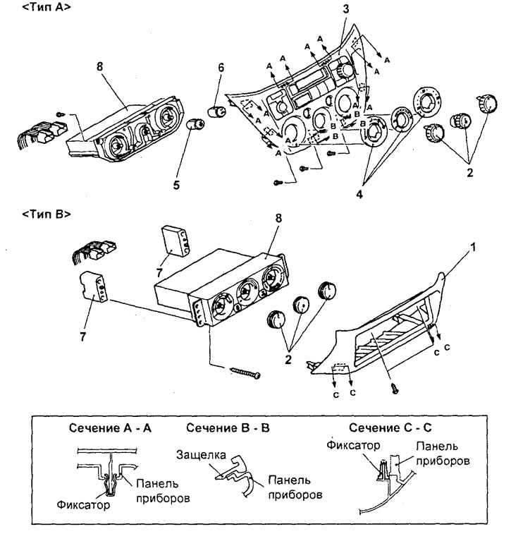
Removal the heater and air conditioner control panel assembly (air conditioner with automatic control). 1 - Additional storage compartment in the lower part of the central trim of the instrument panel, 2 - Air conditioning control switch handles in assembly, 3 - Heater and air conditioning control panel trim, 4 - Heater and air conditioning control panel switch covers, 5 - Rear window defroster switch handle, 6 - Air intake mode selector switch handle, 7 - Heater and air conditioning control panel bracket, 8 - Heater and air conditioning control panel in assembly (air conditioning electronic control unit).
Installation of parts is carried out in the reverse order of removal.
Removal and installation the evaporator assembly
Before you begin removing parts, perform the following operations:
- a) Pump the refrigerant out of the air conditioning system.
- b) Remove the engine and variator control unit.
The parts are removed in the order of the numbers shown in the figure "Removing the evaporator assembly (air conditioner with automatic control)".
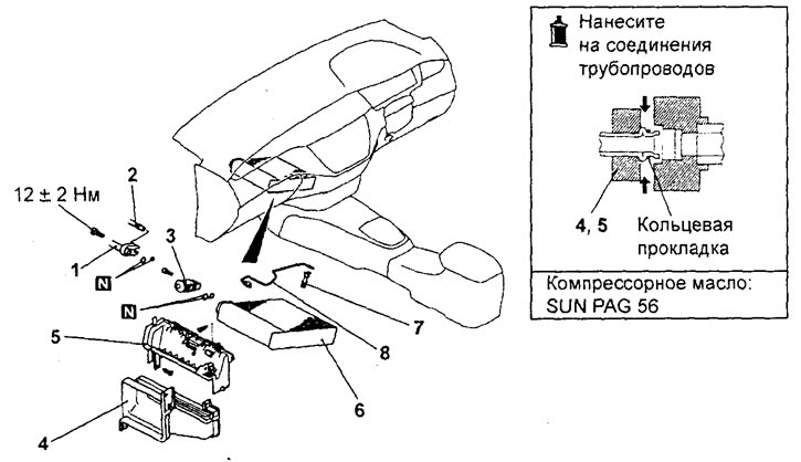
Removal the evaporator assembly (air conditioner with automatic control). 1 - low pressure hose connection, 2 - high pressure tube "B" connection, 3 - expansion valve, 4 - intermediate air duct, 5 - evaporator cover, 6 - evaporator, 7 - evaporator air temperature sensor retainer, 8 - evaporator air temperature sensor.
When removing parts, pay attention to the following operations:
1. Removing the low pressure hose, high pressure tube "B" and expansion valve.
Cover the disconnected tubes and fittings of the evaporator to prevent moisture, dust and other contaminants from entering.
Caution: Hoses must be hermetically sealed, otherwise the compressor oil and receiver-dryer may become saturated with water vapor from the atmosphere. Do not use porous material to close tubes and fittings.
2. Removing the evaporator.
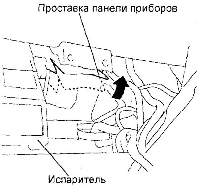
To remove the evaporator without any problems, it is necessary to cut the instrument panel spacer as shown in the figure.
Caution: Do not cut a through hole in the instrument panel spacer.
* Installation of parts is carried out in the reverse order of removal.
Note: When replacing parts, it is necessary to add compressor oil to the system (see section "Work with the air conditioning system").
After completing the installation of the parts, perform the following operations:
- a) Install the engine and variator control unit.
- b) Charge the system with refrigerant.
Removal and installation of servo drives of dampers and electric motor of heater fan
The parts are removed in the order of numbers shown in the figure "Removing the servo drives of the dampers and the electric motor of the heater fan".
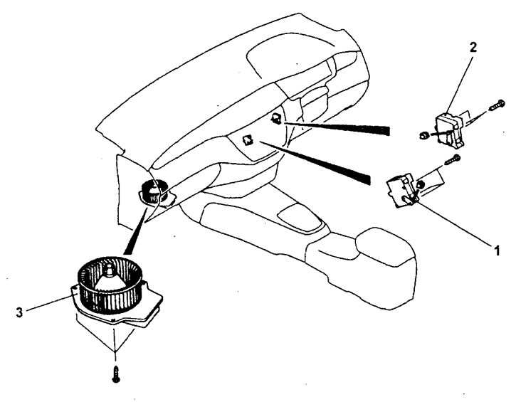
Removal the servo drives of the dampers and the electric motor of the heater fan (air conditioning with automatic control). 1 - air flow mixing flap servo drive and servo drive position sensor, 2 - air intake mode selection flap servo drive and servo drive position sensor, 3 - heater fan electric motor.
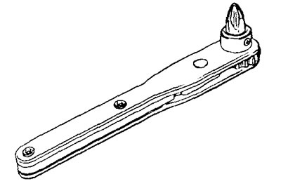
When removing parts, pay attention to the operation of removing the heater fan motor.
Remove the heater fan motor using the special tool shown in the figure.
Installation of parts is carried out in the reverse order of removal.
Removal and installation sensors
The parts are removed in the order of numbers shown in the figure "Removing sensors".
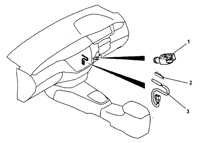
Removal sensors (air conditioning with automatic control).
1 - cabin air temperature sensor (remove the lower air distribution duct (in the footwell area on the passenger side),
2 - retainer,
3 - heater coolant temperature sensor.
Installation of parts is carried out in the reverse order of removal.