



Contents: Removal and installation ⤓ Checking the sunroof actuator switch ⤓ Disassembly and assembly ⤓
Removal and installation
− The parts are removed in the order of the numbers indicated in the figure "Removing the roof hatch".
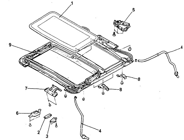
Removal the roof hatch. 1 - sunroof glass assembly; 2 - Sunroof Control Switch Panel; 3 - luxury roof control switch (remove splash guard; ceiling trim and automatic transmission electronic control unit); 4 - drain hose; 5 - Electric motor for sunroof drive; 6 - Sunroof switch mounting bracket 7 - Interior light mounting bracket; 8 - Sunroof mounting bracket; 9 - roof hatch frame with guide assembly.
- When removing parts, pay attention to the following operations:
1. Removing the drain hose.
Tie a sufficiently long cord to the end of the drain hose, wrap the connection with electrical tape so that it is smooth, and then pull out the drain hose.
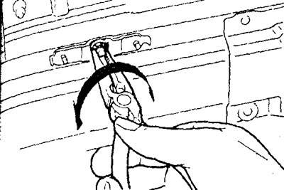
2. Removing the sunroof frame from the guide assembly using a special tool.
Turn the frame mounting screws and tighten it.
Installation of parts is carried out in the reverse order of removal.
When installing parts, please pay attention to the following operations:
1.Installing the drainage hose.
a) Tie a sufficiently long cord (the one used earlier during removal) to the end of the drain hose, wrap the connection with insulating tape so that it is smooth.
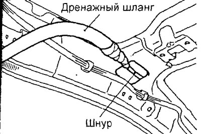
b) Pull the cord to put the drain hose back in place.
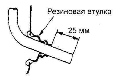
c) Install the rubber bushing and ensure that the drain hose protrudes by the amount shown in the figure.
2. Initializing the sunroof electronic control unit after installing the sunroof drive motor.
Note: This procedure is performed if, after installing the sunroof drive motor, the fully closed positions of the sunroof cover and the electric motor do not match.
a) Set the hatch cover to the "extreme tilt" position by pressing the hatch electric drive switch to the "TILT" position. To accurately set the "extreme tilt" position, the hatch cover should be moved gradually, in several steps, with a stroke of approximately 30 mm per step.
b) Hold the sunroof switch in the "TILT" position for 3 seconds when the sunroof is in the "full tilt" position. Do not release the switch in the forced stop position until the control unit initialization is complete.
c) Set the hatch cover to the "fully closed" position by pressing the hatch electric drive switch to the "CLOSED" position.
d) Set the hatch cover to the "fully open" position by pressing the hatch electric drive switch to the "OPEN" position. The movement of the hatch cover must be continuous throughout its entire travel.
d) Set the hatch cover to the "fully closed" position by pressing the hatch electric drive switch to the "CLOSED" position. The movement of the hatch cover must be continuous throughout its entire travel.
Note: Initialization of the sunroof control module will be completed after the sunroof electric drive has stopped.
- After completing the installation of the parts, perform the following operations:
- a) Adjust the hatch and check the hatch for leaks.
Checking the sunroof actuator switch
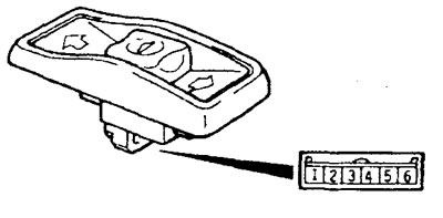
1. Check that the circuit is closed between terminals "4" and "5" of the connector when the switch is in the "OPEN" position.
2. Check that the circuit is open between all connector terminals when the switch is in the "OFF" position.
3. Check that the circuit is closed between terminals "3" and "4" of the connector when the switch is in the "TILT UP" position.
4. Check that the circuit is closed between terminals "4" and "6" of the connector when the switch is in the "TILT DOWN" or "CLOSE" position.
Disassembly and assembly
− The parts are removed in the order of the numbers indicated in the figure "Disassembling the roof hatch".
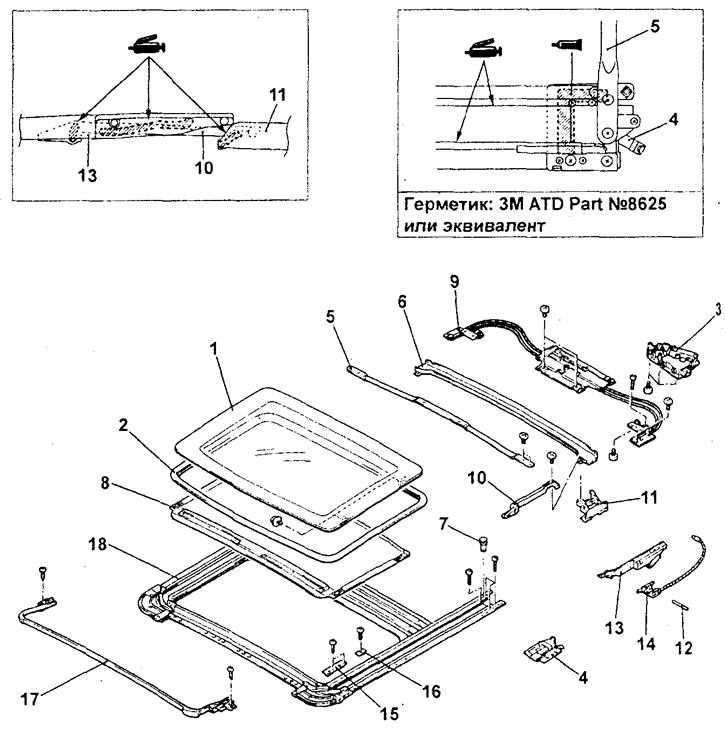
Dismantling the roof hatch. 1 - sunroof glass; 2 - roof hatch seal; 3 - sunroof drive electric motor; 4 - drain gutter cover; 5 - Roof hatch frame reinforcement; 6 - drainage gutter; 7 - one hundred pores; 8 - sunroof curtain assembly; 9 - roof hatch drive mechanism 10 - drain gutter connecting mechanism; 11 - bracket for fastening the drain gutter assembly; 12 - bushing; 13 - roof lift mechanism assembly; 14 - sunroof drive cable assembly; 15 - mounting bracket; 16 - adjusting gasket; 17 - sunroof deflector! assembly; 18 - roof hatch frame assembly.
− Installation of parts is carried out in the reverse order of removal.