Contents: General information ⤓ Table. SWS system fault codes. ⤓ Reading and clearing fault codes ⤓ Checking SWS system signals with a…⤓ Checking the voltage at the…⤓ Table for checking the voltage at…⤓ Table for checking the voltage at…⤓ Table for checking the voltage at…⤓ Table for checking the voltage at…⤓ Table for checking the voltage at…⤓ Table for checking the voltage at…⤓
General information
1. The SWS system enables data exchange between the electrical equipment control unit, the ETACS control unit, the steering column combination switch controller, the main power window switch and the built-in side door power window controllers according to the diagram shown in the figure below.
2. The SWS system ensures the operation of the following systems and functions:
- a) Sound warning function for a key left in the ignition switch;
- b) audible warning function about external lighting being on (when the driver's door is opened);
- c) the function of audible warning of the "R" position of the automatic transmission or CVT selector lever;
- d) Sound warning function on request of the multi-function display;
- d) centralized control function for door locks using the key or the driver's door lock button;
- e) forced door locking function;
- g) forced door unlocking function when the key is left in the ignition;
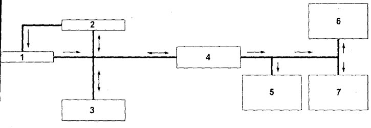
Wiring diagram of the multiplex communication system. 1 - steering column combination switch controller, 2 - ETACS control unit, 3 - electrical equipment control unit, 4 - main window switch, 5 - front passenger door window drive controller, 6 - side door window drive controller (rear right), 7 - side door window drive controller (rear left).
Note: The symbol indicates a unidirectional communication line; the symbol indicates a bidirectional communication line.
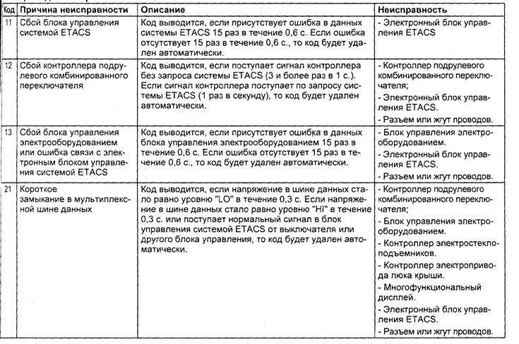
Table. SWS system fault codes.
- c) the function of controlling the door windows from the main window switch;
- i) side door window lift control function from auxiliary window lift switch;
- k) the function of delaying the power supply to the window lifters after the ignition is turned off;
- l) function of fully lowering or raising the driver's door glass;
- m) function to prevent side door glass from getting caught;
- n) remote control function of the central lock from the transmitter key fob;
- o) function of confirmation of operation of the remote control system of door locks (turning on the direction indicators and interior lighting);
- p) sunroof control function;
- r) function of delayed power off of the sunroof after turning off the ignition;
- c) sunroof pinch prevention function;
- t) control function of windshield wipers and washers of the windshield and rear windows (all modes), headlight washers;
- u) electrically adjustable side rear view mirror control function;
- f) electrically adjustable side rear view mirror folding function;
- x) ignition switch illumination control function;
- c) function of controlling side lights and low and high beam headlights;
- w) function of automatic switching on of headlights and side lights;
- щ) control function of side direction indicators and hazard warning lights;
- e) interior lighting control function;
- y) automatic interior lighting shutdown function;
- i) Multifunctional display control function.
Reading and clearing fault codes
Reading and deleting fault codes of the SWS system is performed only with a tester. The procedure for reading codes with a tester is given in the chapter "Fuel injection system (MPI)".
Note: The description of the fault codes is given in the table "SWS system fault codes"
Checking SWS system signals with a tester
Note: This test is performed to check for signals from sensors and switches (ignition switch, key in ignition switch, side door limit switches, hood limit switch, etc.).
Connect the tester and check for signals from the switch being tested using the appropriate function. Switch operation should be confirmed by a sound signal from the buzzer.
If the switch does not operate normally, perform troubleshooting.
Checking the voltage at the terminals of the system component connectors
Note: The system consists of the following components: ETACS control unit, steering column combination switch controller, electrical control unit, power window main switch and power window controllers
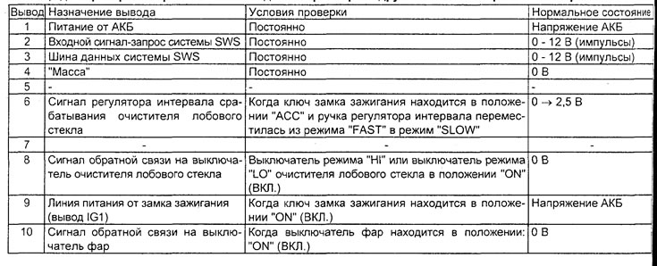
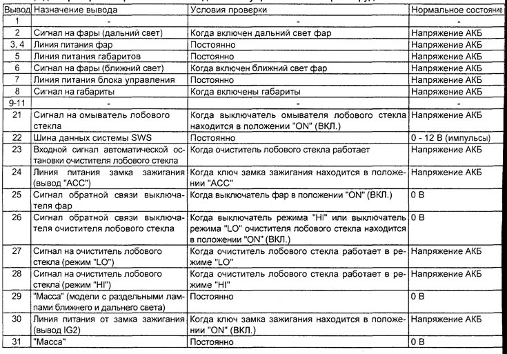
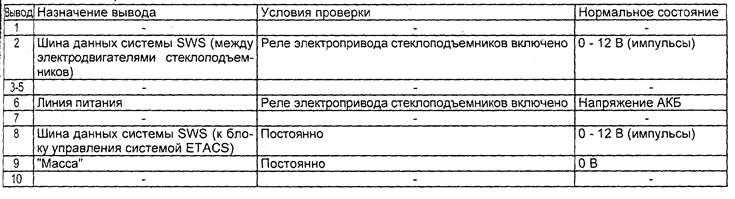
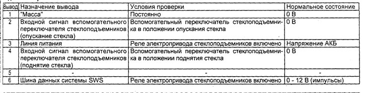
1. Measure the voltage between the ground terminals and each corresponding terminal.
2. The terminals to be tested are indicated in the corresponding tables of voltage tests at the connector terminals.
3. The location of the terminals is shown in the corresponding figures.

ETACS electronic control unit connector.
Table for checking the voltage at the terminals of the electronic control unit of the ETACS system.
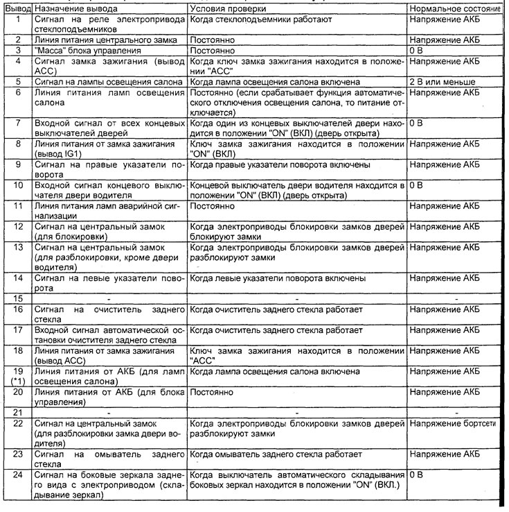
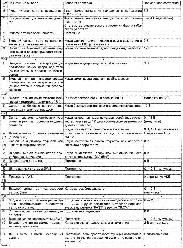
Note: in the table (*¹) - only models produced before 05.2001; (*²) - only for sedan models; (*³) - only for station wagon models.
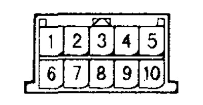
Steering column combination switch controller connector.
Table for checking the voltage at the terminals of the steering column combination switch controller.

Electrical equipment control unit connector.
Table for checking the voltage at the terminals of the electrical equipment control unit.
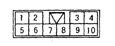
Power window master switch (power window controller) connector.
Table for checking the voltage at the terminals of the main window switch (window controller).
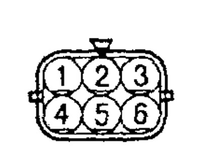
Power window controller connector.
Table for checking the voltage at the terminals of the electric window lifter (window lifter controller).
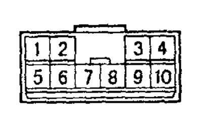
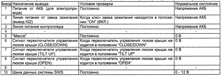
Sunroof electric drive (sunroof controller) connector.
Table for checking the voltage at the terminals of the sunroof electric drive (sunroof controller).