General information
1. The MMCS integrates the navigation system, audio system, air conditioning system, trip computer, TV tuner, self-diagnosis system, help system into a comprehensive vehicle information system.
Attention: the navigation system and TV tuner do not work on the territory of the Russian Federation.
2. Information is displayed using a high-contrast multifunction display located on the central trim of the instrument panel, information is entered using special buttons (See the figure for the location of the buttons "MMCS control buttons").
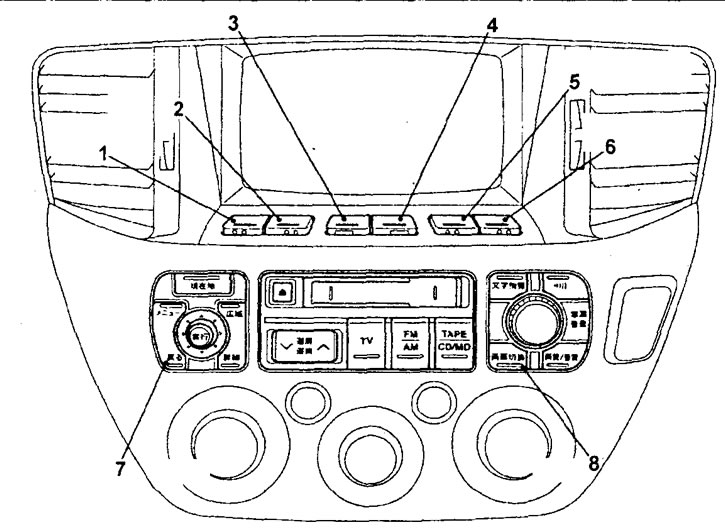
MMCS control buttons. 1 - additional functions button No. 1, 2 - additional functions button No. 2, 3 - additional functions button No. 3, 4 - additional functions button No. 4, 5 - additional functions button No. 5, 6 - additional functions button No. 6, 7 - button to return the display to the previous state, 8 - button to switch display modes.
3. Functions of the service mode of the MMCS system.
Note: To use the service functions, you must enter the service mode.
A) Self-diagnosis function that checks for signals between all units in the system and checks the data bus for errors.
b) A DVD or CD test function that checks the operation of the DVD or CD drive.
Note: if it is impossible to read data from the CD or if the CD is not inserted, then the corresponding inscription appears on the screen.
V) Diagnostic function that checks for signals between all units in the system.
G) An LCD status test function that checks the LCD for dead pixels.
d) An audio test function that tests the performance of the audio system speakers one by one.
e) A function of the navigation system that checks each sensor in the navigation system,
and) Vehicle check function that displays the current state of the vehicle.
h) Navigation system software check function, which displays the version of the loaded software and all units connected to the navigation system unit,
And) Diagnostic results function that displays the appropriate fault code indicating the sensor or control unit when the ignition key is in the "ACC".
To) Data bus test function, which displays data bus errors and fault codes.
l) Data bus error memory function that stores the history of data bus errors.
4. Before troubleshooting, it is recommended that you review the system status table when the battery is disconnected.
Table. MMCS memory states after disconnecting the wires from the battery terminals.
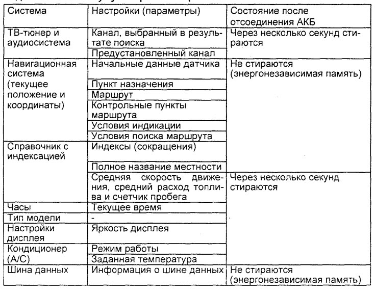
Attention: on models with the MMCS system, a large amount of data is stored in the memory of the control units of various systems, which will be erased after disconnecting the power (battery). Therefore, it is recommended to remember the settings of the most important systems and read the trouble codes before disconnecting the wire from the negative terminal of the battery.
Features of system diagnostics
1. Malfunctions of the MMCS system can be caused by malfunctions, due to which the communication between various control units is disrupted. Therefore, it is necessary to check the service functions and self-diagnosis functions.
2. If a DTC appears for any system, first check that the wiring harness connector is properly connected to the connector itself.
3. If the problem persists, then the cause of the problem is probably in the wiring harness or control unit. Check the wiring harness and if it is not correct, replace the control unit assembly. Record the fault code before replacing the unit.
Features of diagnostics of the MMCS system interface
1. If there is a symptom of a malfunction of the MMCS interface, then it is necessary to check the service function (MMCS display), special button operation and screen operation.
2. If a DTC appears for the MMCS system, first check the correct connection of the harness connector and the connector itself.
3. If the problem persists, then the cause of the problem is probably in the wiring harness or the corresponding unit. Check the wiring harness and if it is not correct, replace the assembly.
Operation in service mode
1. To enter the service mode:
- A) Turn the ignition key to position "OFF".
- b) While holding down the Auxiliary Function Button #6 and the MMCS Display Mode Switch button, turn the ignition on. Keep the buttons pressed for 5 seconds, after switching on the ignition, the first menu of the service mode will appear on the display.
Note:
- If the first menu of the service mode does not appear, then you need to perform all the operations from the beginning.
- To enter a specific function of the service mode, press the buttons No. 1 - No. 4 of additional functions.
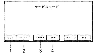
The first menu of the service mode. 1 - LCD status check function, 2 - self-diagnosis check function, 3 - system settings, 4 - diagnostic function.
2. After the system has entered the first menu of the service mode, to enter the second menu of the service mode, press the button No. 5 of additional functions.
Note: to return to the first menu of the service mode, also press the button No. 5 of additional functions.
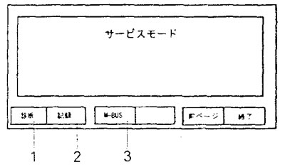
The second menu of the service mode.1 - self-diagnosis function, 2 - diagnostic results function, 3 - data bus error memory function.
3. To exit the service mode, press the button No. 6 of additional functions or turn the ignition key to the position "OFF".
Reading and clearing diagnostic trouble codes
1. To enter the diagnostic results function menu in the second menu of the service mode, press the button No. 2 of additional functions.
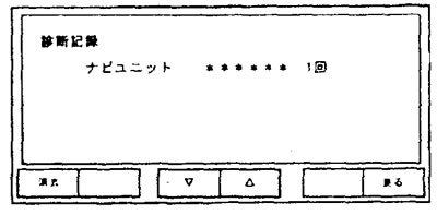
Diagnosis result function menu.
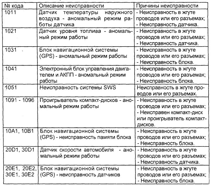
2. Determine the location of the malfunction according to the received diagnostic codes in accordance with "MMCS Trouble Code Table", repair the problem, then repeat the test procedure.
Table. Codes of malfunctions of the MMCS system.
3. To delete the displayed fault codes in the menu of the diagnostic results function, press the button No. 1 of additional functions. The display will prompt you to confirm the deletion of codes. To delete the codes, press button No. 5 of additional functions, and to return to the diagnostic results function menu without deleting fault codes, press button No. 6 of additional functions.
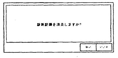
Request for confirmation of deletion of the fault code.
4. To exit the menu of the diagnostic results function, press the button No. 6 of additional functions.
Removing and installing MMCS components
- Parts are removed in the order of the numbers shown in the figure "Removing MMCS components".
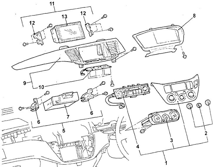
Removing MMCS components. 1 - heater and air conditioner control panel assembly, 2 - air conditioner control switch handles assembly, 3 - heater and air conditioner control panel (air conditioning electronic control unit), 4 - MMCS control panel, 5 - audio unit assembly, 6 - audio unit mounting bracket, 7 - audio unit, 8 - instrument cluster trim, 9 - instrument panel center trim, 10 - MMCS additional functions button panel, 11 - multifunction display assembly, 12 - multifunction display mounting bracket, 13 - multifunction display.
− Installation of parts is carried out in the reverse order of removal.
Removal and installation of the navigation system unit (GPS)
Attention: this system does not work on the territory of the Russian Federation.
- Parts are removed in the order of the numbers shown in the figure "Removing the navigation system unit".
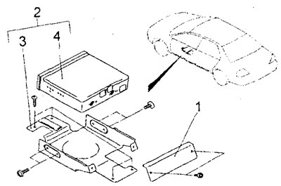
Removing the navigation system unit (sedan). 1 - side mounting bracket for the navigation system unit, 2 - navigation system unit assembly, 3 - lower mounting bracket for the navigation system unit, 4 - navigation system unit.
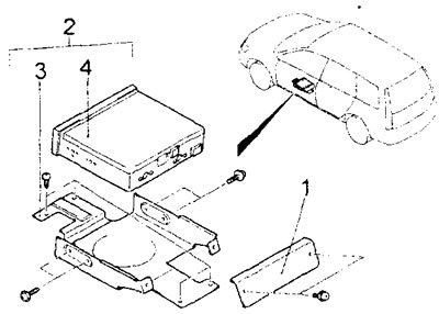
Removing the navigation system unit (station wagon). 1 - side mounting bracket for the navigation system unit, 2 - navigation system unit assembly, 3 - lower mounting bracket for the navigation system unit, 4 - navigation system unit.
− Installation of parts is carried out in the reverse order of removal.
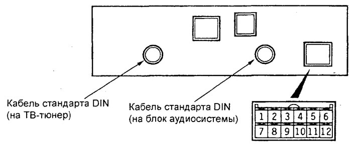
Removing and installing the DIN cable
1. Remove the lower part of the central trim of the instrument panel.
2. Remove the CD changer.
3. Remove the audio system unit.
4. Remove the navigation system unit.
5. Remove the instrument panel and center console.
6. Remove the front seat assembly.
7. Remove the floor mat.
8. Remove the DIN cable.
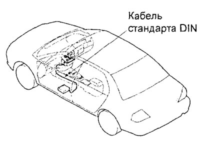
sedan models
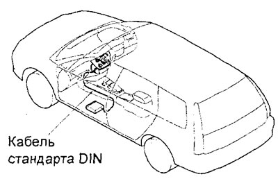
Station wagon models
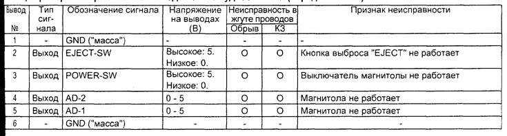
Checking the voltage at the terminals of the connectors of the MMCS blocks
1. Measure the voltage between the terminal "masses" vehicle and each corresponding output of the MMCS unit.
2. The location of the pins is shown in the corresponding figures.
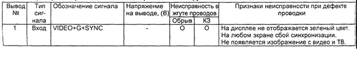
3. The nominal voltage value for each test output is indicated in the corresponding table.
4. The voltage ratings of the terminals are indicated in the test tables for voltage at the terminals of the connectors of the corresponding units of the MMCS system.
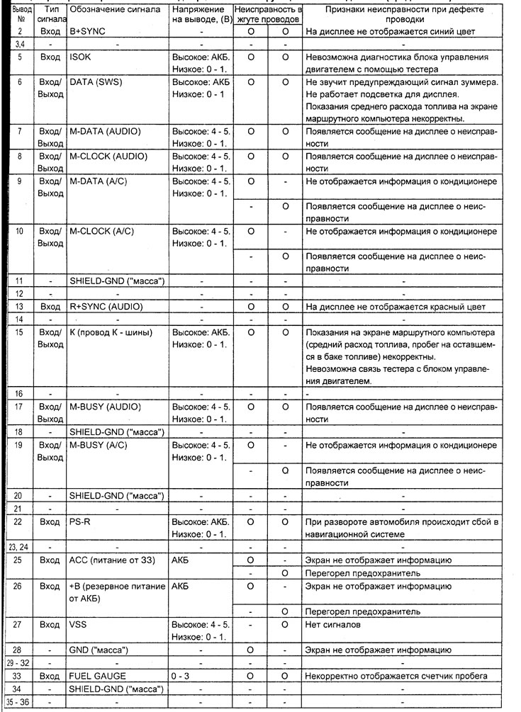
Table note: "cliff" - means a break in the circuit, "KZ" - means short circuit, "33" - ignition lock, voltage "battery" - this is the voltage of the onboard network.
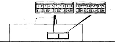
Multifunction display connectors
Table. Checking the voltage at the terminals of the multifunction display connector.
Connectors of the navigation system unit.
Table for checking the voltage at the terminals of the navigation system unit.
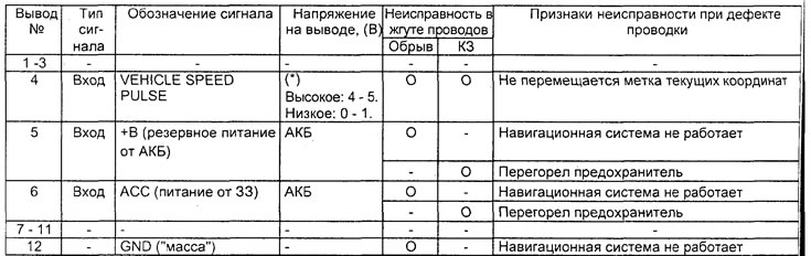
Note: (*) - as the wheels rotate, the voltage will change.
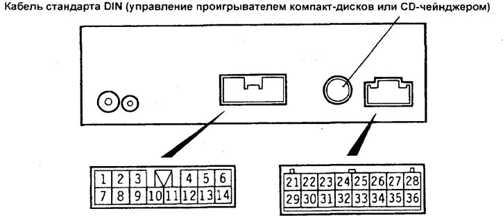
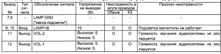
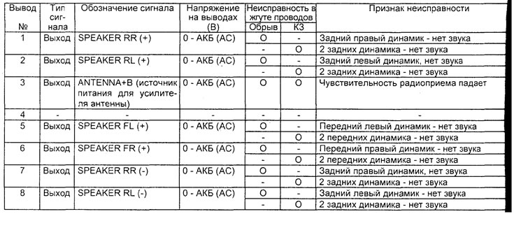
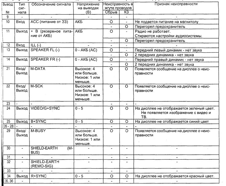
Audio unit connectors (rear end).
Table for checking voltage at the terminals of the audio system unit (rear end).
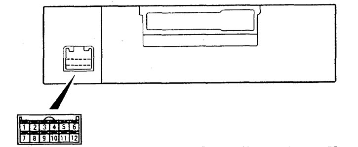
Audio unit connector (front end).
Table for checking voltage at the terminals of the audio system unit (front end).