Contents: Headlight adjustment ⤓ Measuring headlight brightness ⤓ Adjusting the front fog lights ⤓ Removal and installation headlights ⤓ Removal and installation the light…⤓ Checking the light sensor ⤓ Removal and installation front fog…⤓ Removal and installation front fog…⤓ Checking the front fog light switch ⤓ Table: Checking the front fog light…⤓ Removal and installation side turn…⤓ Removal and installation the rear…⤓ Removal and installation an…⤓ Removal and installation license…⤓ Removal and installation the floor…⤓ Checking the floor light switch ⤓ Table. Checking the switch. ⤓ Removal and installation the hazard…⤓ Checking the hazard warning switch ⤓ Table. Switch testing. ⤓
Note: For replacement of lamps, see chapter "User manual".
Headlight adjustment
Preparing for headlight adjustment
1. Check the headlight assemblies for faults, corrosion, and component defects. Eliminate faults before adjusting.
2. Adjust the tire pressure to the nominal value.
3. (If the headlight range control switch is installed) Set the headlight range control switch to the "0" position.
4. Let the engine run at 2000 rpm to fully charge the battery.
5. If the fuel tank is not full, place a load in the luggage compartment at a rate of 0.8 kg per liter of fuel.
6. Leave only one driver in the car, or place a load weighing 55 kg in his place.
7. Wipe the headlight lenses thoroughly.
8. Determine the center of the headlight for which adjustment will be made.
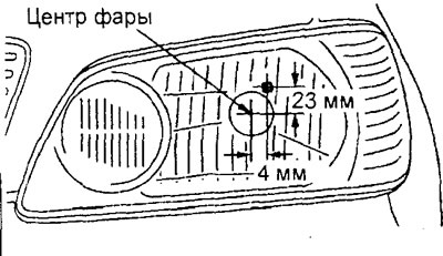
Models with single high and low beam lamps.
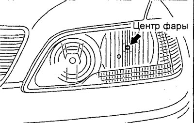
Models with separate high and low beam lamps.
9. The headlight beam should be adjusted using appropriate lighting devices in compliance with the instructions of the manufacturer of these devices.
Note: If your region has special requirements regarding vehicle lighting, adjust the headlights to meet these requirements.
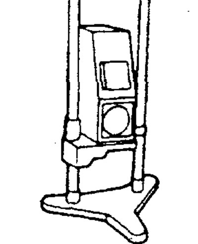
10. Place the vehicle on a level horizontal surface so that the distance from the center of the headlight to the lighting device is 1 m, as shown in the figure.
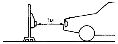
11. General recommendations for adjustment.
Attention:
- To avoid deformation of the plastic headlight lens, do not cover the headlight for more than three minutes.
- When adjusting one headlight, make sure the other headlight is disconnected by disconnecting the connector.
- When connecting the headlight connector after completing the adjustment, make sure that the headlight setting is not lost.
Note: If external lighting makes it difficult to determine the cut-off point of the headlight beam, use a curtain or additional screen to reduce the influence of external lighting.
Headlight adjustment (according to European standards)
1. Check that the headlight beam is positioned correctly on the screen.
a) Check for a clear light-shadow boundary and an asymmetrical beam image relative to the vertical line.
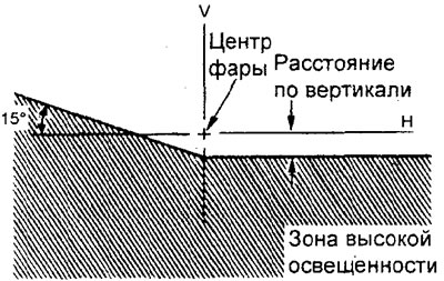
b) In the vertical direction, the beam of light from the headlights must be below the horizontal line "H" by the specified amount.
Nominal value - 7 mm
c) In the horizontal direction, the angle at which the inclined line of the headlight beam intersects the vertical line "V" must correspond to the nominal value.
Nominal value - 15°
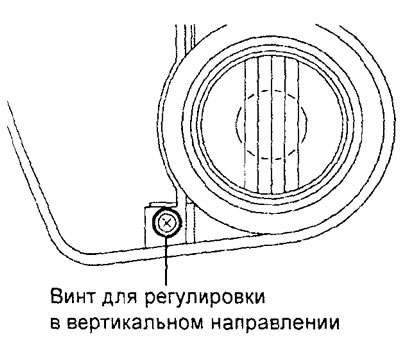
2. To adjust the position of the headlight beam, rotate the corresponding adjusting screws one by one.
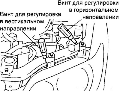
Models with single high and low beam lamps.
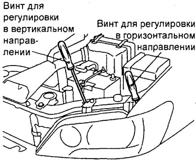
Models with separate high and low beam lamps.
Measuring headlight brightness
1. Place the vehicle on a level horizontal surface so that the distance from the center of the headlight to the lighting device is 1 m.
2. Turn on the low beam headlights and, following the instructions of the device manufacturer, measure the brightness of the headlights using a photometer and check that the measured value corresponds to the nominal value.
The maximum permissible value is not less than 6400 Candela
Note:
- When measuring the light brightness, keep the engine speed at least 2000 rpm to keep the battery in a charged state.
- If a luxmeter is used to measure the brightness of light, then it is necessary to convert its readings into photometer units of measurement using the following formula:
I= ER², Where
- I - brightness of light, Candela (cd),
- E - illumination, (lux),
- R is the distance in meters from the headlight to the lux meter.
Adjusting the front fog lights
Preparing to adjust the front fog lights
1. Check the front fog lamp assemblies for faults, corrosion, and component defects. Eliminate faults before adjusting.
2. Adjust the tire pressure to the nominal value.
3. Let the engine run at 2000 rpm to fully charge the battery.
4. If the fuel tank is not full, place a load in the luggage compartment at a rate of 0.8 kg per liter of fuel.
5. Leave only one driver in the car, or place a load weighing 55 kg in his place.
6. Wipe the fog light lenses thoroughly.
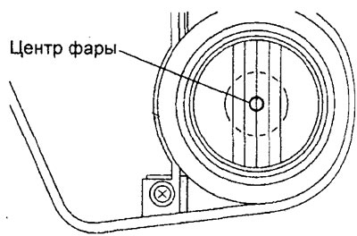
7. Determine the center of the front fog light to be adjusted as shown in the figure.
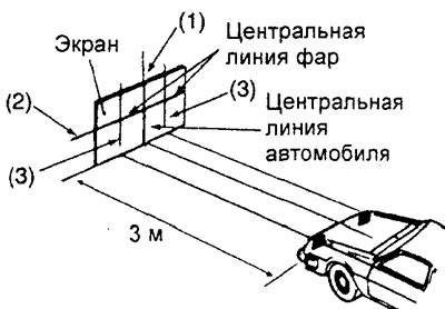
8. Place the vehicle on a level, horizontal surface so that the distance from the center of the front fog lamp to the screen is 3 m, as shown in the figure.
9. Rock the car horizontally (left-right) to achieve a stable position.
10. Rock the vehicle vertically three times, applying force to the hood or front bumper to stabilize the front suspension.
11. Draw four lines on the screen for adjustment.
a) Position the vertical line so that it coincides with the center line of the car (the longitudinal axis of the car).
b) Measure the distance (height) from the center of the front fog lamp to the pad and mark the value on the screen. This horizontal line will be used as a reference line for vertical adjustment.
Adjusting the front fog lights
1. Check that the position of the fog light beam on the screen is normal.
a) In the vertical direction, the beam of light from the headlights (cut-off line) must be located within the specified range below the horizontal line "H" by the specified amount.
Nominal value: 6 cm (1.15°)
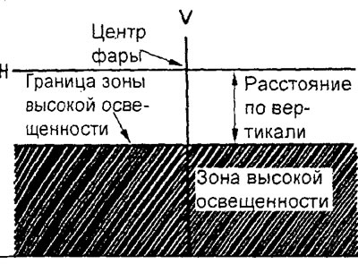
b) In the horizontal direction, the beam of light from the headlights should be parallel to the direction of travel of the vehicle.
Original version of the article on the website [mitsubishiman.ru]
Note: The fog lights cannot be adjusted horizontally. If the beam of light from the headlights deviates from the nominal position, check that the headlights are correctly mounted and that there are no defects in the mountings.
2. To adjust the position of the fog light beam in the vertical direction, rotate the adjusting screw.
Caution: When adjusting, be sure to cover other lamps (lighting devices) that are not being adjusted.
Removal and installation headlights
The parts are removed in the order of the numbers indicated in the figure "Removing the headlights".
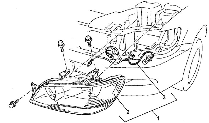
Removal headlights.1 - headlight assembly, 2 - headlight, 3 - sockets with wiring assembly.
Installation of parts is carried out in the reverse order of removal.
After completing the installation of the parts, adjust the headlights.
Removal and installation the light sensor
The parts are removed in the order of the numbers indicated in the figure "Removing the light sensor".
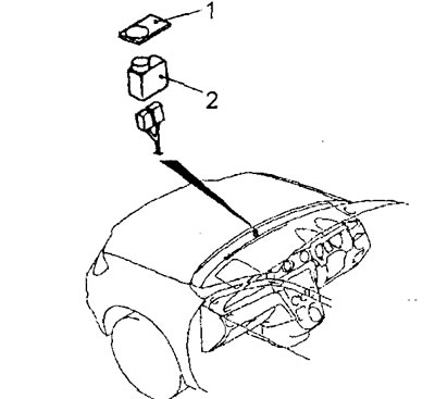
Removal the light sensor.1 - light sensor cover, 2 - light sensor.
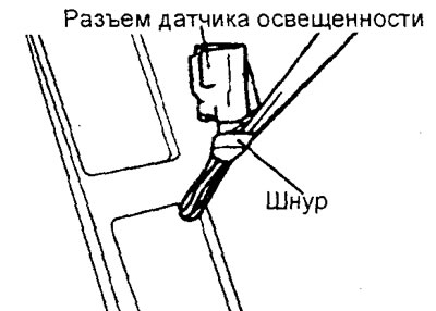
When removing parts, pay attention to the operation of removing the light sensor.
Tie a sufficiently long cord to the light sensor connector, wrap the connection area with electrical tape so that it is smooth, and then remove the light sensor from the top of the instrument panel.
Installation of parts is carried out in the reverse order of removal.
Checking the light sensor
If the headlights turn on when the sensitive side of the light sensor is covered with a hand and the steering column combination switch for exterior lighting is in the "AUTO" position, the light sensor is OK. If the headlights do not turn on, replace the light sensor.
Removal and installation front fog lights (station wagon)
Before you begin removing parts, remove the front bumper grille.
The parts are removed in the order of the numbers indicated in the figure "Removing the front fog light".
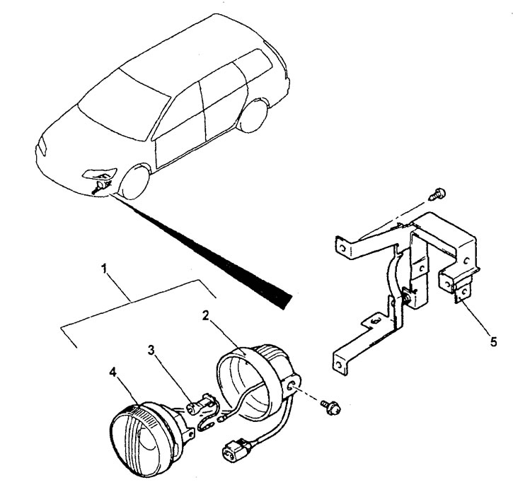
Removal the front fog light. 1 - front fog light assembly, 2 - cover, 3 - lamp, 4 - front fog light, 5 - front fog light mounting bracket.
When removing parts, pay attention to the operation of removing the front fog lamp bulb.
Before removing the front fog light bulb, release the bulb retaining spring.
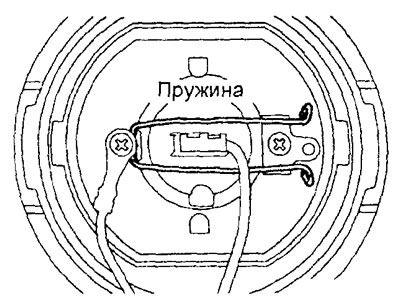
Installation of parts is carried out in the reverse order of removal.
After completing the installation of the parts, install the front bumper decorative grille.
Removal and installation front fog light switches
The parts are removed in the order of the numbers shown in the figure "Removing the front fog light switch".
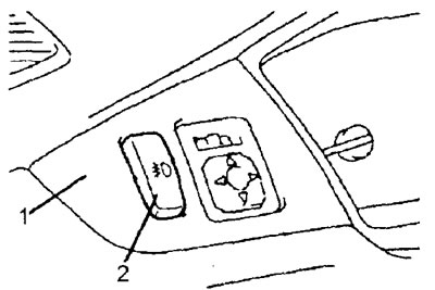
Removal the front fog light switch. 1 - instrument panel trim on the driver's side, 2 - front fog light switch.
Installation of parts is carried out in the reverse order of removal.
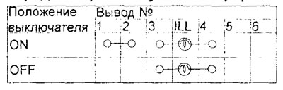
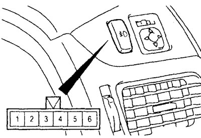
Checking the front fog light switch
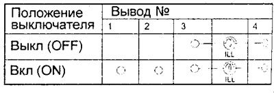
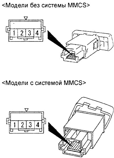
Check the condition of the circuit between the terminals of the switch connector at different positions of the switch according to the table provided.
Table: Checking the front fog light switch.
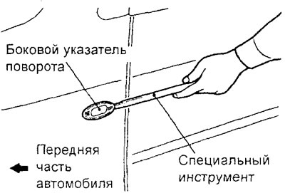
Removal and installation side turn signals
1. Using the special tool, pry the side turn signal and remove it from the front fender panel.
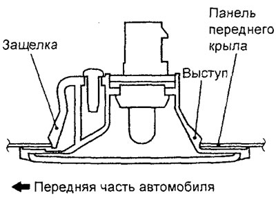
2. To install the side turn signal, follow these steps:
- a) Insert the side turn signal into the front fender panel.
- b) Press the side turn signal and secure it with the latch.
Removal and installation the rear combination light
The parts are removed in the order of the numbers shown in the figure "Removing the rear combination light".
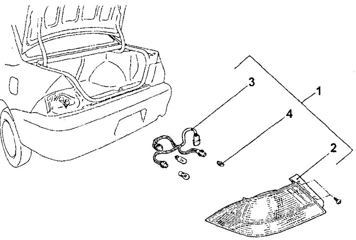
Removal the rear combination light (sedan) 1 - rear combination light assembly, 2 - rear combination light, 3 - sockets with wiring assembly, 4 - lamp.
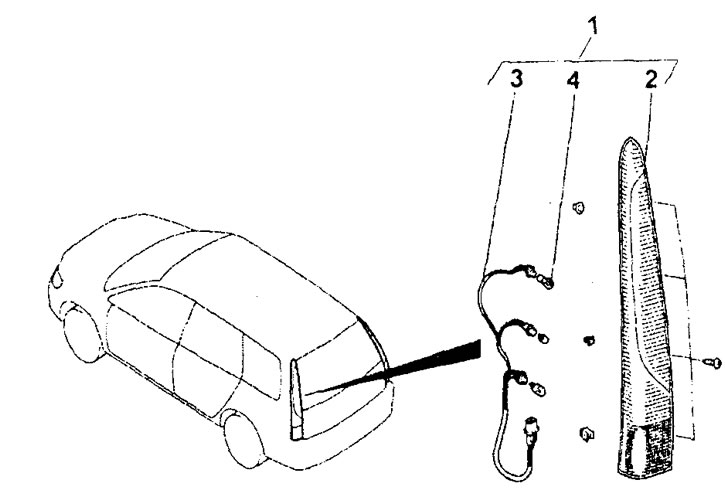
Removal the rear combination light (station wagon). 1 - rear combination light assembly, 2 - rear combination light, 3 - sockets with wiring assembly, 4 - lamp.
−Installation of parts is carried out in the reverse order of removal.
-(Station wagon) When installing the parts, pay attention to the installation operation of the rear combination light assembly.
When installing the rear combination light, tighten all mounting screws securely.
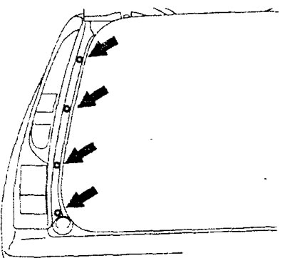
Removal and installation an additional brake light
(Universal) Before you begin removing parts, perform the following operations:
- a) Remove the upper rear door trim.
- b) Disconnect the additional brake light connector.
- c) Disconnect the rear door window washer hoses.
The parts are removed in the order of the numbers indicated in the figure "Removing the additional brake light".
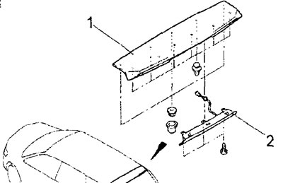
Removal an additional brake light (station wagon). 1 - spoiler (remove the rear door window washer nozzle), 2 - additional top signal.
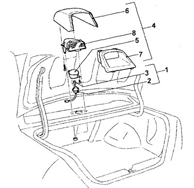
Removal an additional brake light behind the rear window (sedan).1 - socket with lamp assembly, 2 - socket, 3 - lamp, 4 - additional brake light assembly, 5 - socket holder, 6 - upper cover of additional brake light, 7 - lower cover of additional brake light, 8 - additional brake light.
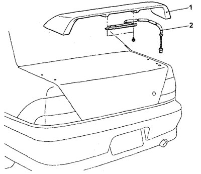
Removal an additional brake light on a spoiler (sedan). 1 - spoiler, 2 - additional brake light.
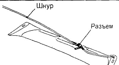
(Sedan models with additional brake light on the spoiler) When removing the parts, pay attention to the operation of removing the additional brake light.
Tie a sufficiently long cord to the additional brake light connector, wrap the connection area with insulating tape so that it is smooth, and then carefully remove the additional brake light.
Installation of parts is carried out in the reverse order of removal.
After completing the installation of the parts, perform the following operations:
- a) Install the upper section of the rear door.
- b) Connect the rear door window washer hoses.
- c) Connect the additional brake light connector.
Removal and installation license plate light bulbs
The parts are removed in the order of the numbers indicated in the figure "Removing the foot plate illumination lamps".
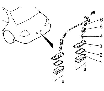
Removal license plate light bulbs (sedan). 1 - license plate light bulb diffuser, 2 - seal, 3 - license plate light bulb housing, 4 - license plate light bulb, 5 - bulb socket, 6 - wire harness.
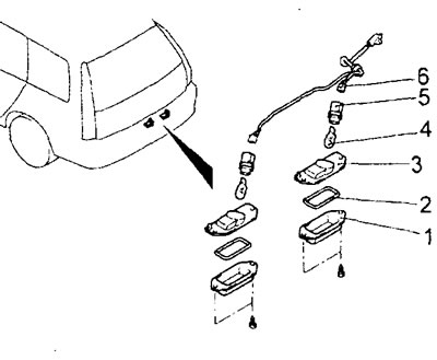
Removal license plate light bulbs (station wagon). 1 - license plate light bulb diffuser, 2 - seal, 3 - license plate light bulb housing, 4 - license plate light bulb, 5 - bulb socket, 6 - wire harness.
Installation of parts is carried out in the reverse order of removal.
Removing and installing the engine compartment light
1. Press the engine compartment light clips as shown in the figure and remove the light.
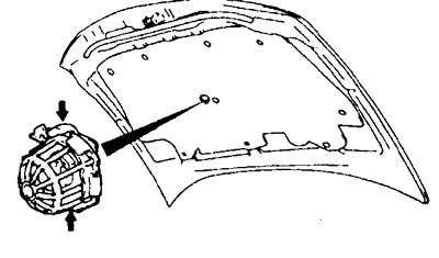
2. Installation of parts is carried out in the reverse order of removal.
Removal and installation the floor lighting lamp
The parts are removed in the order of the numbers indicated in the figure "Removing the floor lighting lamp".
Installation of parts is carried out in the reverse order of removal.
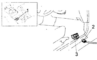
Removal the floor lighting lamp. 1 - Floor light switch (remove lower instrument panel trim on driver's side), 2 - floor light connector, 3 - floor light.
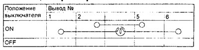
Checking the floor light switch
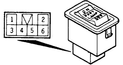
Check the condition of the circuit between the terminals of the switch connector at different positions of the switch according to the table provided.
Table. Checking the switch.
Removal and installation the hazard warning switch
The parts are removed in the order of the numbers indicated in the figure "Removing the hazard warning switch".
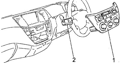
Removal the hazard warning switch (models with MMCS). 1 - heater and air conditioner control panel assembly, 2 - hazard warning switch.
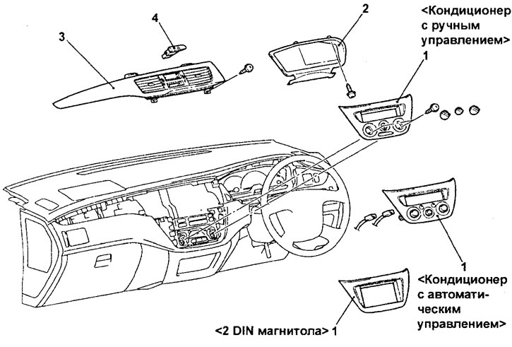
Removal the hazard warning switch (models without MMCS). 1 - heater and air conditioner control panel assembly or radio trim, 2 - instrument cluster trim, 3 - central instrument panel trim, 4 - hazard warning switch.
Installation of parts is carried out in the reverse order of removal.
Checking the hazard warning switch
Check the condition of the circuit between the terminals of the switch connector at different positions of the switch according to the table provided.
Table. Switch testing
.