



Contents: Checking the speedometer ⤓ Table. Nominal values of speedometer…⤓ Checking the tachometer ⤓ Table. Nominal values. ⤓ Checking the fuel gauge ⤓ Checking the fuel level sensor ⤓ Table. Nominal values. ⤓ Checking the engine coolant…⤓ Checking the Engine Coolant…⤓
Checking the speedometer
Note: A possible cause of a speedometer malfunction is a faulty vehicle speed sensor, a broken wire harness, or a fault in the speedometer itself.
1. Adjust the tire pressure to the nominal value.
Warning: Avoid mixing tyre/rim types and sizes as this will adversely affect driving safety and the accuracy of the speedometer/odometer readings.
2. Place the vehicle on chocks and place chocks under the rear wheels.
2WD models
Check that the parking brake is applied.
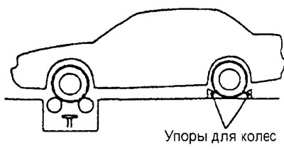
2WD models
4WD models
Securely attach the rear wheel support casters to the floor so that they are positioned in line with the wheelbase and tire treads as shown in the illustration.
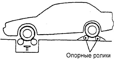
4WD models
3. To prevent the front wheels from shifting from side to side, attach two tensioners to the vehicle"s towing hooks and secure the ends of the tensioners to the support plates.
4. To prevent the vehicle from moving forward, attach one end of the cable to the rear towing hook and securely attach the other end of the cable to the support plate.
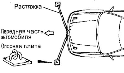
5. Check that the speedometer readings are within the nominal range.
Table. Nominal values of speedometer readings.
| Speed, km/h | Acceptable range of values, km/h |
| 40 | 37-45 |
| 80 | 75-88 |
| 120 | 113-132 |
| 160 | 150-176 |
Caution: Do not allow sudden increase/decrease in speed during testing.
The original can be found on the website [MITSUBISHIMAN]
Checking the tachometer
Note: Possible causes of tachometer failure include damage to the power supply circuit, poor contact with ground, lack of input signal from the engine control unit, or a fault in the tachometer itself.
1. To check the tachometer without a tester, insert a paper clip into the tachometer service connector on the wiring side and connect a test tachometer.
Note: To check the standard tachometer of the car, it is recommended to use a tachometer with an inductive type sensor, which is connected to the high-voltage spark plug wire.
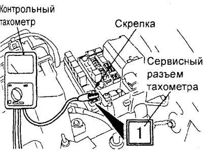
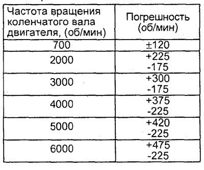
2. With the engine running, compare the readings of the standard tachometer with the readings of the tester or control tachometer at each set engine crankshaft speed. If the error of the standard tachometer exceeds the permissible value, replace the tachometer.
Attention:
- - Incorrect connection of the tachometer (reversal of power supply polarity) will result in its damage.
- - Be careful when replacing the tachometer, do not drop it or allow it to hit other parts.
Table. Nominal values.
Checking the fuel gauge
1. Disconnect the fuel level sensor (2WD models) or main fuel level sensor (4WD models) connector from the fuel pump base.
2. Connect a lamp (12 V - 3.4 W) between terminals "1" and "2" of the connector on the wire harness side.
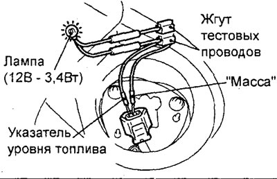
2WD models.
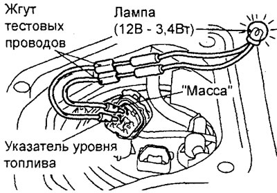
4WD models.
3. Turn the ignition key to the "ON" position.
4. Check the lamp condition. If the lamp does not light, check the connectors and wiring, repair if necessary.
5. If the lamp lights up, check the condition of the fuel gauge arrow. If the arrow remains stationary, replace the indicator.
6. If the lamp lights up and the fuel level indicator arrow moves toward the middle position, then the fuel level sensor in the tank is faulty.
Checking the fuel level sensor
Note: To check, remove the fuel level sensor from the fuel tank (see chapter "Fuel injection system").
1. Checking the resistance of the fuel level sensor.
a) Check that the resistance between the fuel level sensor terminal and the ground terminal corresponds to the nominal value when the sensor float is at the highest point "F" and the lowest point "E".
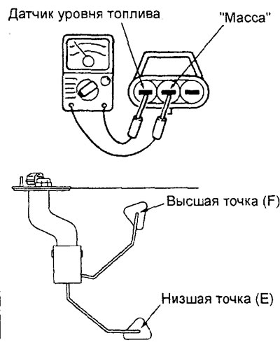
2WD models.
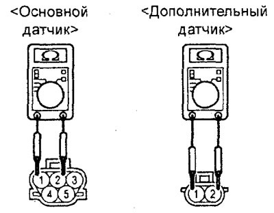
4WD models.
Nominal values:
2WD models:
- Highest point "F" - 3±1 Ohm
- Lowest point "E" - 110±1 Ohm
4WD models:
Main sensor:
- Highest point "F" - 2±1 Ohm
- Lowest point "E" - 40.6±1 Ohm
Additional sensor:
- Highest point "F" - 2 ±1 Ohm
- Lowest point "E" - 69.4±1 Ohm
b) Check that the resistance value changes smoothly when the float is slowly moved between the highest point "F" and the lowest point "E".
c) If the test results do not match those specified, replace the sensor.
2. Checking the movement of the fuel level sensor float.
Moving the float until it touches the stops, measure the height "A" at the highest point "F" and the height "B" at the lowest point "E".

2WD models.
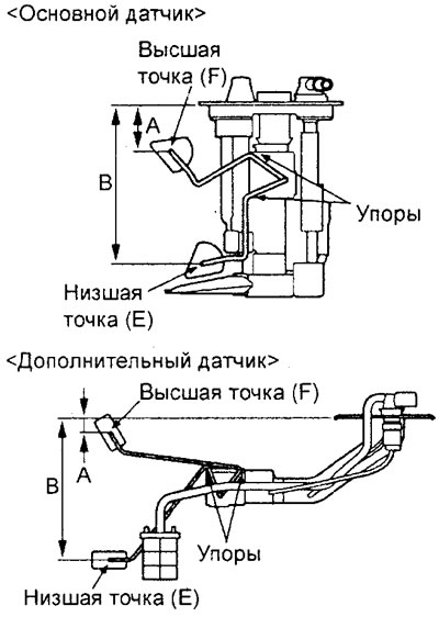
4WD models.
Table. Nominal values.
| Sensor | A (mm) | B (mm) |
| 2WD | 24,4±1 | 151,6±2 |
| Sensor | A (mm) | B (mm) |
| 4WD-main | 40,5 ±4 | 136 + 4 |
| 4WD-additional | 15,8 | 154 |
Checking the engine coolant temperature gauge
1. Disconnect the engine coolant temperature sensor connector (on the pointer).
2. Connect a lamp (12V - 3.4W) between the connector on the wire harness side and ground.
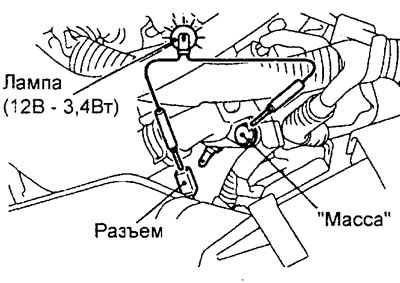
Models with 4G15 engine.
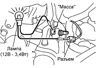
Models with 4G93 engine.
3. Turn the ignition key to the "ON" position.
4. Check the lamp condition. If the lamp does not light, check the connectors and wiring, repair if necessary.
5. If the lamp lights up, check the condition of the coolant temperature gauge arrow. If the arrow remains stationary, replace the gauge.
6. If the lamp lights up and the coolant temperature gauge arrow moves toward the middle position, then the coolant temperature gauge sensor is faulty.
Checking the Engine Coolant Temperature Gauge Sensor
Note: For removal and installation of the coolant temperature gauge sensor, see the chapter "Cooling system".
1. Place the measuring part of the sensor in hot water at 70°C and measure the resistance between the sensor terminals.
Nominal value (at 70°C) - 104±13.5 Ohm
Reference values:
| Temperature (°C) | Resistance (Ohm) |
| 50 | 230 |
| 60 | 155 |
| 80 | 73 |
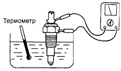
2. If the resistance does not match the specified value, replace the sensor.
Note: Apply sealant to the engine coolant temperature gauge sensor threads before installation.