



Removal
Caution: Avoid impacting the SRS electronic control unit when removing and installing the CVT control cable.
- Before starting the removal:
- a) Remove the battery and battery bracket.
- b) Remove the lower part of the center console (see chapter "Body").
− The parts are removed in the order of the numbers indicated in the figure "CVT control mechanism".
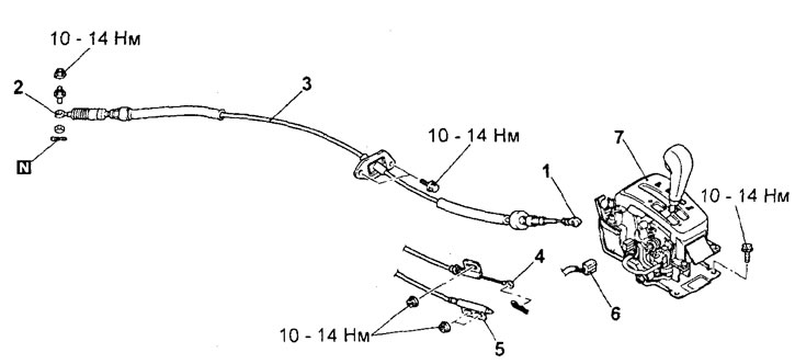
Variator control mechanism. 1 - CVT control cable connection (from the selector side), 2 - CVT control cable connection (from the CVT side), 3 - CVT control cable, 4 - ignition lock cable, 5 - CVT selector lock cable, 6 - selector position indicator connector (models without manual gear shift mode) / gear position sensor connector (models with manual gear shift mode), 7 - CVT selector assembly.
(Information copied from the website: «MitsubishiMan.ru»)
Disassembly and assembly
When disassembling the selector, refer to the assembly drawing "CVT selector".
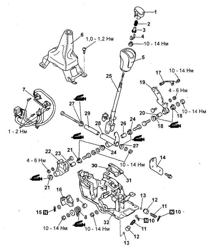
CVT selector (models with manual shift mode and selector cover). 1 - button, 2 - spring, 3 - cap, 4 - regulator, 5 - selector handle, 6 - selector casing, 7 - selector position sensor, 8 - return spring, 9 - bushing, 10 - cotter pin, 11 - spring, 12 - ball retainer, 13 - ball, 14 - plate, 15 - cotter pin, 16 - locking cam, 17 - retainer spring, 18 - bushing, 19 - lever assembly, 20 - lever bushing, 21 - bushing, 22 - plate, 23 - plate bushing, 24 - bushing, 25 - selector lever, 26 - bushing, 27 - tube bushing, 28 - outer tube, 29 - inner tube, 30 - retainer "A", 31 - retainer "B", 32 - selector bracket assembly.
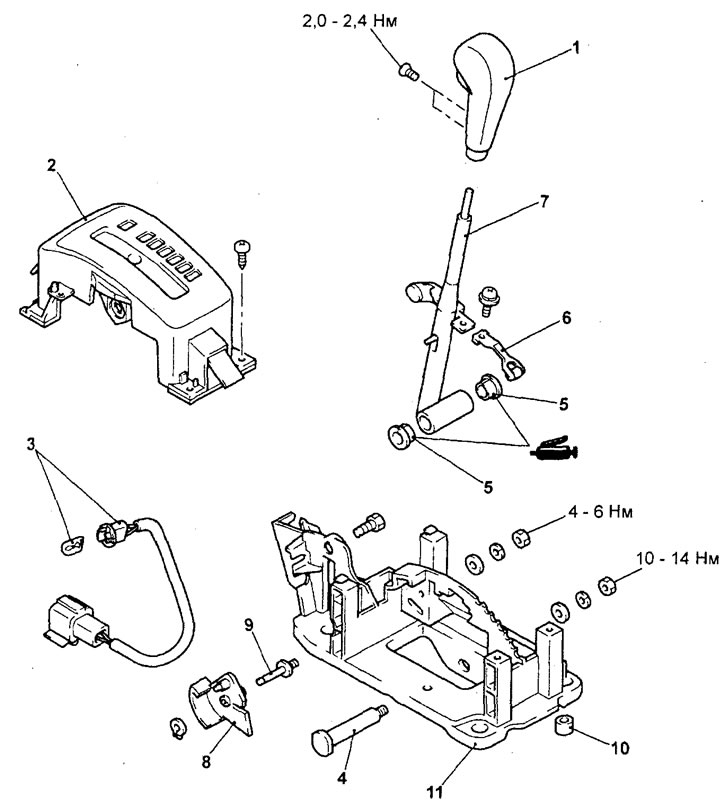
CVT selector (models without manual gear shift mode).1 - selector handle 2 - selector position indicator panel, 3 - selector position indicator, 4 - bolt, 5 - bushing, 6 - locking spring, 7 - selector lever, 8 - locking cam, 9 - pin, 10 - bushing 11 - selector bracket.
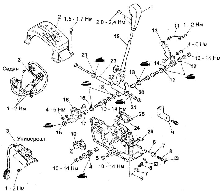
CVT selector (models with manual gear shift mode and selector position indicator panel). 1 - selector handle, 2 - selector position indicator panel, 3 - selector position sensor, 4 - return spring, 5 - sleeve, 6 - ball, 7 - ball retainer, 8 - spring, 9 - plate, 10 - locking cam, 11 - retainer spring, 12 - sleeve, 13 - lever assembly, 14 - lever sleeve, 15 - sleeve, 16 - plate, 17 - plate sleeve, 18 - sleeve, 19 - selector lever, 20 - sleeve, 21 - tube sleeve, 22 - outer tube, 23 - inner tube, 24 - retainer "A", 25 - retainer "B", 26 - selector bracket assembly.
Assembly is carried out in the reverse order of disassembly.
Installation
− Installation of parts is carried out in the reverse order of removal.
- After installation is complete:
- a) Install the lower part of the center console (see chapter "Body").
- b) Install the battery bracket and battery.
- Check the operation of the variator selector (see section "Basic checks and adjustments").