



Contents: Toe-in ⤓ Convergence angle (Toe-out) when…⤓ Camber, caster (longitudinal angle…⤓ Rear wheel alignment (Toe-in) ⤓ Checking the play in the front hub…⤓
Check the condition of the outer surface of the vehicle tires. If uneven tire wear is detected, check and, if necessary, adjust the wheel alignment angles.
Toe-in
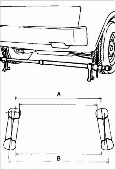
Using a special ruler, measure the toe-in of the steered wheels. Toe-in = B – A
Recommended value: At the center of the tire tread: 1±2 mm Toe angle (per wheel): 0° 03+05.
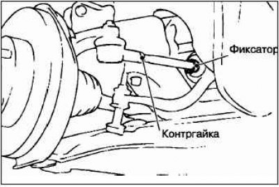
Adjust the wheel alignment by first removing the lock and unscrewing the lock nut by rotating the screw tightening sleeves of the right and left steering rods in different directions, but by the same amount.
Note: The wheel alignment will tend to be negative if you turn the left turnbuckle towards the front of the vehicle and the right turnbuckle towards the rear of the vehicle.
Install the retainer and tighten the lock nut to the recommended tightening torque. Recommended tightening torque: 52 + 2 N·m.
Make sure the wheel toe is within the recommended range.
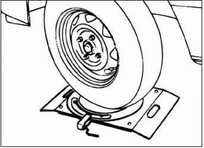
Using the swivel disc, check that the steering wheel angle matches the recommended value.
Recommended value:
- inner wheels: 34°5' ±1°3'
- outer wheels: 29°2'
Convergence angle (Toe-out) when turning the car
To check the condition of the steering rods, especially if the car has been in an accident (or is suspected of having been in an accident), it is highly recommended to check the toe-in angle of the wheels (Toe-out) when turning the vehicle in addition to the standard wheel alignment check. Perform this check when turning left and right.
Recommended value: convergence angle (Toe-out) when turning (for the outer wheel, when the inner wheel has an angle of 20°): 22°0' ±1°30'.
Camber, caster (longitudinal angle of kingpin inclination), transverse angle of kingpin inclination
- Camber: – 0°10' ±30'
- Castres: 3°15' ±30'
- KPI: 12°25" ±1°30"
Note: The difference between the right and left wheel should not exceed 30'.
The longitudinal and transverse angles of the kingpin are set at the factory and cannot be adjusted.
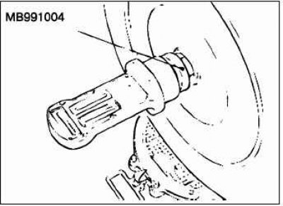
For cars with aluminum wheels, secure the reflectors to the drive shaft tail using the MB991004 clamp. The tightening torque of the special tool should be equal to the tightening torque of the drive shaft nut (245±29 N·m).
Caution: To avoid damaging the wheel bearing, do not allow the weight of the vehicle to impact the wheels when the drive shaft mounting nuts are loose.
Rear wheel alignment (Toe-in)
Recommended value: at the center of the tire tread: 3±2 mm.
Toe angle (per wheel): 0°08' ±0.5'.
Make sure that the camber adjustment is performed before the toe adjustment.
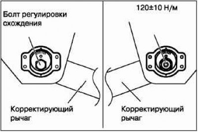
To adjust the toe-in of the rear steering wheels, it is necessary to turn the toe-in adjustment bolts (the bolts that secure the adjusting levers on the inside of the body).
Left wheel: turn the bolt clockwise (+) – the toe-in increases.
Right wheel: turn the bolt counterclockwise (–) – the toe-in increases.
Note: The scale is graduated approximately 2.6 mm (one wheel toe is equivalent to 16')
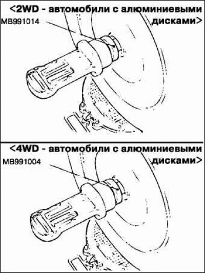
Recommended value: –0°40 ±30' (difference between right and left wheel: no more than 30')
Note. The camber is set at the factory and is not adjustable. For 2WD vehicles with aluminum wheels, secure the reflector to the trailing arm axle using the special tool (MB991014). Tighten the special tool to a tightening torque equal to the tightening torque of the trailing arm axle 175±25 N·m. For 4WD vehicles with aluminum wheels, secure the reflectors to the drive shaft tailstock using the locking tool MB991004. The tightening torque of the special tool should be equal to the tightening torque of the drive shaft nut (245±29 N·m).
Checking the play in the front hub bearings
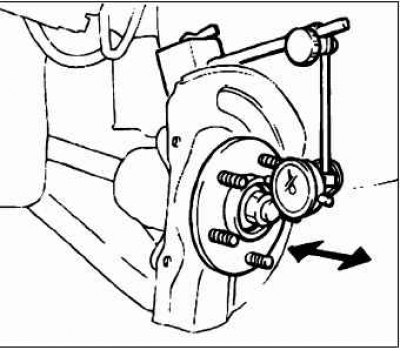
Disconnect the front brake caliper and, without disconnecting the brake hose, hang the caliper near the wheel hub.
Remove the brake disc from the hub.
Attach a dial indicator as shown in the figure. Measure the axial play in the hub bearing by moving it back and forth.
Limit value: 0.05 mm.
If the axial clearance exceeds the permissible value, replace the hub assembly.