



Contents: Vacuum booster ⤓ Master brake cylinder ⤓ Front brake mechanism ⤓ Rear brake mechanism ⤓ Parking brake ⤓ Anti-lock braking system (ABS) ⤓ Anti-lock braking system (EBD) ⤓
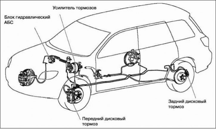
Mitsubishi Outlander cars are equipped with two independent brake systems: service and parking. The first system, equipped with a hydraulic drive, provides braking when the car is moving, the second - brakes the car when parked, its drive is mechanical.
The vehicle uses a service brake system with diagonally divided circuits, which significantly increases driving safety. If one of the circuits of the service brake system fails, the second circuit is used, which ensures the vehicle stops, although with less efficiency. Both circuits are activated by one pedal, which is attached to the body bracket. In addition to the brake pedal, the hydraulic drive includes a vacuum booster, a master brake cylinder, front and rear brake mechanisms together with working cylinders, and pipelines.
The parking system is driven by the brake mechanisms of the rear wheels.
Vacuum booster
Installed between the brake pedal mechanism and the main brake cylinder, during braking due to the vacuum in the intake pipe (receiver) of the engine through the rod and piston of the first chamber of the main cylinder creates additional force proportional to the force from the pedal. A check valve is installed in the hose connecting the vacuum booster to the intake pipe (receiver). It maintains the vacuum in the booster when it drops in the intake pipe and prevents the fuel-air mixture from entering the vacuum booster.
Master brake cylinder
The main brake cylinder of the hydraulic brake drive consists of two separate chambers connected to independent hydraulic circuits. The first chamber is connected to the right front and left rear brake mechanisms, the second - to the left front and right rear brake mechanisms.
The master cylinder is equipped with a tank, the internal cavity of which is divided by a partition into two sections. Each section feeds one of the chambers of the master cylinder.
When the brake pedal is pressed, the pistons of the master cylinder begin to move, the working edges of the cuffs cover the compensation holes, the chambers and the reservoir are disconnected and the displacement of the brake fluid begins. On cars equipped with an anti-lock braking system (ABS), the fittings of the tubes supplying brake fluid to the ABS hydraulic unit are screwed into the holes of the master brake cylinder.
On cars without ABS, pressure regulators are installed on the main brake cylinder, which, when braking, adjust the brake fluid pressure in the rear brake mechanisms, eliminating the possibility of early locking of the rear wheels. This is achieved by a proportional decrease in the pressure in the rear brakes in relation to the pressure in the front.
Front brake mechanism
The front wheel brakes are disc brakes with automatic adjustment of the gap between the brake pads and the disk, with a floating bracket. The movable bracket is formed by a caliper with a single-piston working cylinder. The pad guide is bolted to the front suspension steering knuckle. The movable bracket is bolted from below to the guide pin, which is installed in the hole in the pad guide; from above, the bracket moves along the guide pin screwed into the shoe guide. The guide pin and the guide pin are lubricated with consistent grease and protected by rubber covers. A piston with a sealing ring is installed in the cavity of the wheel cylinder. Due to the elasticity of this ring, an optimal gap is maintained between the shoes and the ventilated disc, the surface of which is protected by the brake shield. When braking, the piston, under the influence of fluid pressure, presses the inner shoe to the disc, as a result of the reaction force, the caliper moves on the fingers and the outer shoe is also pressed to the disc, and the pressing force of the shoes is the same. When releasing the brakes, the piston is moved away from the shoe due to the elasticity of the sealing ring, a small gap is formed between the shoes and the disc.
Rear brake mechanism
The rear wheel brakes are drum-type, with automatic adjustment of the gap between the shoes and the drum. The brake shoes are actuated by one hydraulic working cylinder with two pistons. The optimum gap between the drum and the shoes is maintained by the automatic adjustment mechanism of the gap between the drum and the shoes.
Parking brake
The parking brake is mechanically actuated and consists of a traction lever with an adjusting nut and two cables. The rear cable ends are connected to the parking brake actuator release levers mounted on the rear brake shoes. The lever, secured between the front seats on the floor tunnel, is equipped with a cable tension adjustment mechanism. The front cable ends are connected to the tension mechanism equalizer.
The parking brake does not require special maintenance. During routine repairs, check the degree of wear of its parts, make sure that the sector teeth and pawl are in good condition. Replace excessively worn parts.
If any breaks in the cable sheaths or wires are detected, they must be replaced with new ones.
Anti-lock braking system (ABS)
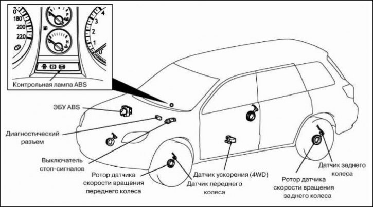
The vehicles are equipped with an anti-lock braking system (ABS) with an electronic brake force distribution system (EBD). ABS regulates the pressure in the brake mechanisms of all wheels during braking, preventing the wheels from locking; ensures a reduction in braking distance during emergency braking while maintaining vehicle stability and control.
The anti-lock braking system includes an ABS electronic control unit, a hydraulic unit, a vacuum booster, a master cylinder, wheel speed sensors and pipelines.
The electronic control unit and the ABS hydraulic unit, combined into a single module, are installed in the engine compartment under the brake booster and secured to the front panel (for clarity, the photo was taken with the brake booster removed).
When the vehicle is braking, the ABS electronic control unit receives a signal from all wheel speed sensors and determines which wheel is currently on the verge of locking. Based on the signals received, the electronic unit activates the corresponding electromagnetic valve in the hydraulic unit to ensure the required pressure in the pipeline of the corresponding wheel.
The electronic control unit of the ABS has built-in self-diagnostics and emergency mode functions. If the electronic control unit detects a malfunction in the system, the anti-lock brake system malfunction indicator lamp lights up in the instrument cluster and the corresponding malfunction code is written into the memory of the electronic control unit, which is read using a special diagnostic device (scanner). If a malfunction occurs in the ABS, the braking system remains operational, but the wheels may lock when braking the car.
Anti-lock braking system (EBD)
Electronic Brakeforce Distribution (EBD) is a subsystem of ABS that serves to ensure effective traction of the rear wheels with the road surface.
With the EBD system, the braking force is maintained close to optimal and is regulated by an electronic system, which makes it possible to do without a pressure regulator.
The electronic brake force distribution system is controlled by the ABS electronic unit. When the vehicle is moving, the brake force distribution system constantly determines the degree of slippage of each wheel of the vehicle and regulates the pressure of the working fluid in the brake mechanisms of the front wheels so that it exceeds the pressure in the brake mechanisms of the rear wheels. As a result, locking of the rear wheels is prevented and higher efficiency of brake operation is ensured.
If a malfunction occurs in the EBD system, the brake system status indicator lamp (with a red light filter) lights up in the instrument cluster.