



Contents: Adjusting the hood ⤓ Adjusting the front and rear side…⤓ Adjusting the trunk lid (sedan) ⤓ Rear Door Adjustment (Wagon) ⤓ Adjusting the side door glass ⤓ Adjustment in case of failure of the…⤓ Checking the operation of the window…⤓ Checking the stroke of the inside…⤓ Checking the travel of the outside…⤓ Checking the travel of the outer…⤓ Checking the current in the window…⤓ Checking the central lock ⤓ Checking the thermal fuse (built…⤓ Checking the hatch for leaks ⤓ Adjusting the hatch ⤓ Checking the operation of the…⤓ Checking the load (current) of the…⤓
Adjusting the hood
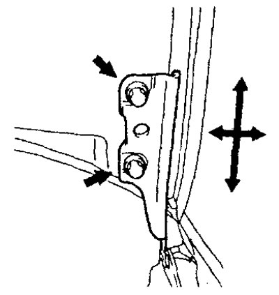
1. Loosen the hood mounting bolts and, by moving the hood, adjust its position so that the gap on all sides is the same.
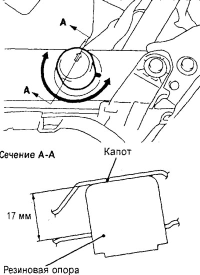
2. Adjust the height of the hood by turning the rubber hood supports.
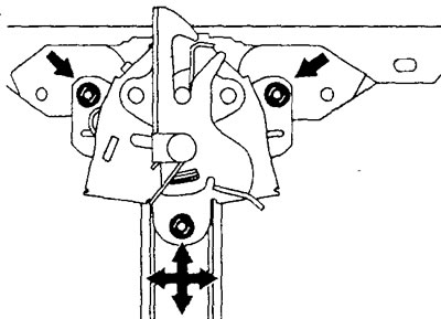
3. Loosen the hood lock mounting bolts and, by moving the hood lock, adjust the relative position of the lock and the hood lock retainer.
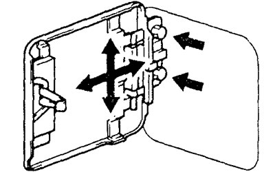
Adjusting the fuel filler door Loosen the fuel filler door mounting screws and adjust the position of the fuel filler door so that the gap between the fuel filler door and the vehicle body is the same around the entire perimeter of the door.
Adjusting the front and rear side doors
1. If the gap around the perimeter between the side door and the body is uneven, stick protective tape on the body around the hinge and on the edge of the door, then use a special tool to loosen the bolts securing the door hinge to the body. By moving the door, adjust the gap between the door and the body so that the gap is the same around the entire perimeter of the door.
Caution: Do not apply force exceeding 98 N to the special tool.
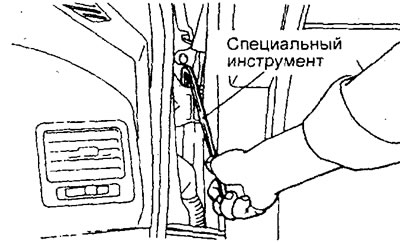
For front right door.
2. If the closed door is not flush with the body surface, use a special tool to loosen the hinge bolts on the door and adjust the position of the door so that its surface is flush with the body surface.
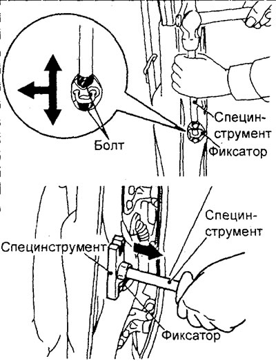
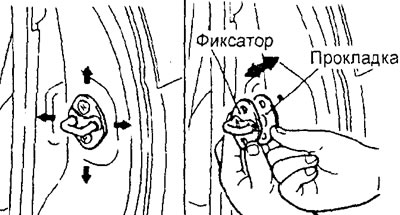
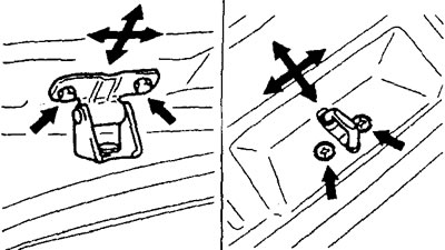
3. If it is difficult to open and close the door, adjust the engagement of the lock and the door latch by installing additional shims between the latch and the body pillar and moving the latch either up and down or right and left.
Adjusting the trunk lid (sedan)
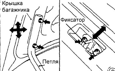
Loosen the bolts securing the lock and the trunk lid, and adjust the engagement of the lock and the lock retainer of the trunk lid and the gap between the trunk lid and the body.
Rear Door Adjustment (Wagon)
1. If it is difficult to open and close the door, adjust the engagement of the lock and the door lock retainer by moving the lock retainer either up and down or right and left.
2. If the gap around the perimeter between the rear door and the body is uneven, loosen the bolts securing the door hinges and the lock retainer and adjust the gap by moving the hinges or changing the number of adjusting shims (total thickness).
Adjusting the side door glass
Check the smoothness of the movement of the side door glass along the glass guide when raising and lowering the glass to the extreme positions. If the side door glass does not move up and down smoothly, adjust as follows:
1. Remove the side door trim and waterproof film.
2. Raise the side door glass to the extreme position, then loosen the bolts securing the glass to the holder on the window regulator through the service holes and adjust the position of the glass in the vertical direction.
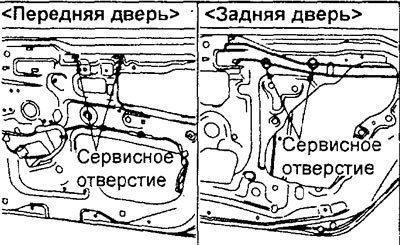
3. After completing the adjustment, securely tighten the bolts securing the glass to the holder.
Adjustment in case of failure of the side door window lifter
Note: This adjustment is made if the side door glass automatically starts to move down when you press the switch to raise the glass.
1. Remove the side door trim and waterproof film.
2. Lower the side door glass to the extreme position, then disconnect the glass from the holder on the window regulator. Raise and lower the side door glass by hand to check the operating force.
Caution: Install a soft buffer inside the side door to prevent damage to the glass if it accidentally falls.
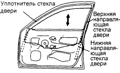
3. If the side door glass does not move up and down smoothly, perform the following checks and, if necessary, repair the parts:
- a) Check that the side door glass seal is installed correctly.
- b) Eliminate twisting of the upper guide of the side door glass.
- c) Check that the lower guide of the front side door glass or the central guide of the rear side door glass is installed correctly.
Note: The lower side door glass track is not adjustable, but can be moved outward during reinstallation, within the manufacturer's tolerance.
4. If repair or adjustment is not possible, replace the side door assembly.
Checking the operation of the window lift safety mechanism
1. Place a wooden block about 10mm thick as shown in the picture, then lift up the side door glass.
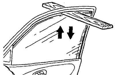
2. Check that the window has dropped approximately 150 mm after clamping the block. If the window lifter does not operate as specified, the cause may be a faulty window lifter limit switch, a defective connector or wiring harness, a faulty auxiliary window lifter switch or main window lifter switch, or an incorrectly adjusted limit switch.
Checking the stroke of the inside handle for opening the side door
1. Check that the stroke "A" of the inner side door opening handle corresponds to the nominal value.
Nominal value (V):
- Front side doors - 9.6 ±9.2 mm
- Rear side doors - 9.0±9.2 mm
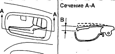
2. If the stroke of the outside side door opening handle does not correspond to the nominal value, remove the side door trim and adjust the stroke of the handle by changing the relative position of the clamps and the rod of the inside side door opening handle.
Checking the travel of the outside handle of the side door
1. Check that the stroke "B" of the outside handle of the side door corresponds to the nominal value.
Nominal value (A):
- Front side doors - 2.3 ±2.1 mm
- Rear side doors - 1.3±1.7 mm
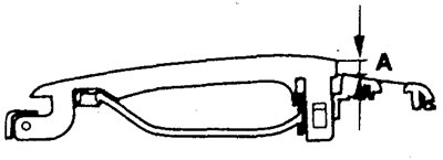
2. If the stroke of the outside side door handle does not correspond to the nominal value, check and, if necessary, replace the outside side door handle or the side door lock assembly.
Checking the travel of the outer handle of the rear door (station wagon)
1. Check that the stroke "C" of the outer handle of the rear door corresponds to the nominal value.
Nominal value (B) - 2.3-5.9 mm
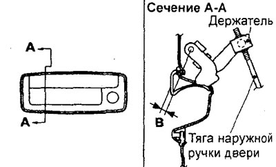
2. If the stroke of the rear door outer handle does not correspond to the nominal value, check the rear door outer handle and rear door lock assembly (adjust the rear door outer handle rod). Replace the parts if necessary.
Checking the current in the window lifter electric drive circuit
1. Remove the power window circuit fuse and connect the tester as shown in the figure.
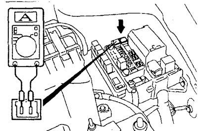
2. When the window lift switch is moved to the "UP" position, the maximum current appears in the period of time between the start of the window lifting and its extreme position (the window is completely raised). Therefore, the current strength should be measured in the range between these two positions.
Nominal value - 5±1 A (at a temperature of 25°C and a voltage of 14.5 ±0.5 V)
3. If the load (current) does not correspond to the nominal value, the cause may be a malfunction of the window lifter electric drive, a malfunction of the window lifter switch, a defect in the connector or wiring harness.
Checking the central lock
1. Check that when you unlock/lock the front side door with the key or the driver's door with the interior lock button, all doors are automatically unlocked/locked.
The original can be found on the website (mitsubishiman.ru)
2. Check that the driver's door can be opened using the inside side door release handle when all doors are locked. Also check that all doors, including the trunk lid (sedan) or tailgate (wagon), unlock at the same time. If this does not happen, replace the driver's door lock assembly.
3. Check that the driver's door does not lock if you press the side door lock button with the driver's door open. If the driver's door locks, replace the door lock.
Checking the thermal fuse (built into the window lift motor)
1. Move the window switch to the "UP" position, raise the glass fully and continue to hold the switch in this position for 10 seconds (when the thermal fuse is triggered, it makes a characteristic click).
2. Release the switch and immediately move it to the "DOWN" position. The thermal fuse is OK if the glass starts moving down within 60 seconds.
Checking the hatch for leaks
1. Close the sunroof glass completely.
2. Adjust the water pressure so that the water jet rises to a height of approximately 50 cm from the hose when placed vertically.
3. Position the hose approximately 30 cm above the vehicle roof and spray the sunroof seal with water for 5 minutes or more.
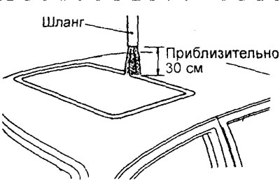
4. Check for water leakage into the vehicle interior through the sunroof seals.
5. If a leak is detected, check the hatch seals, drain hose and other hatch parts.
Adjusting the hatch
1. Close the sunroof glass completely and open the sunroof blind completely.
2. Loosen the sunroof assembly mounting screws and move the sunroof to adjust its position so that the sunroof glass at the front is 1 mm below the roof surface and at the rear is 1 mm above the roof surface.
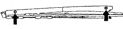
3. Tighten the hatch cover assembly screws securely.
4. After completing the adjustments, check the smooth operation of the sunroof electric drive.
Checking the Power Sunroof Delay Function After Power is Turned Off The power sunroof operates when the ignition switch is turned to the "ON" position or for 30 seconds after the ignition switch is turned off. If any door is opened or the sunroof is completely closed within 30 seconds after the ignition switch is turned off, the sunroof will not operate until the ignition switch is turned on.
Checking the operation of the sunroof safety mechanism
1. Place a wooden block about 10mm thick on the right corner of the sunroof glass, then close the sunroof.
2. Check that after clamping the block, the sunroof glass returns to its original position.
Checking the load (current) of the sunroof glass drive
1. Remove the sunroof circuit fuse and connect the tester as shown in the figure.
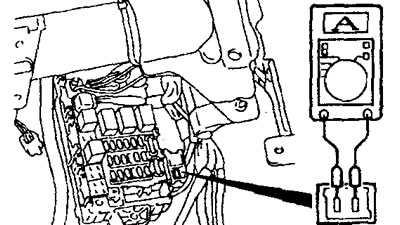
2. Press the switch to the "ON" position and measure the load (current) while the sunroof glass is moving. Do not measure when the sunroof glass is at the extreme tilt position or when the sunroof glass is fully closed or when the sunroof glass is fully opened.
Nominal value: 7A or less (at 20°C)