



Contents: Mirage (all) and Galant models since…⤓ Galant models 1994÷1998. ⤓ Models Diamante (all) and Galant…⤓
Caution! To avoid damage to the ROM components, wear a special bracelet to remove static electricity when servicing the ECM/PCM!
Mirage (all) and Galant models since 1999.
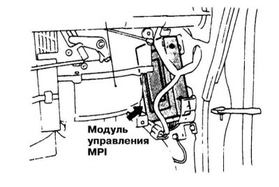
1. On these models, the PCM is located at the bottom of the vehicle's front passenger door pillar (above the front sill plate).
2. Disconnect the negative cable from the battery.
Warning! If the car stereo system is equipped with a security code, make sure you have the correct combination to activate the audio system before disconnecting the battery!
3. Disconnect the wiring harness, release the fasteners and remove the PCM assembly.
4. Installation is carried out in reverse order.
Galant models 1994÷1998.
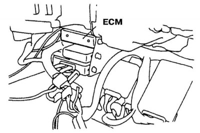
1. The location of the control module on Galant models produced in 1994–1998 is shown in the illustration.
2. Disconnect the negative cable from the battery.
Warning! If the car stereo system is equipped with a security code, make sure you have the correct combination to activate the audio system before disconnecting the battery!
3. Remove both side sections of the center console.
4. Disconnect the electrical wiring, remove the fasteners and remove the control module assembly from the vehicle.
5. Installation is carried out in reverse order.
Models Diamante (all) and Galant 1990÷1993.
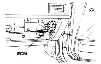
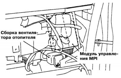
1. The location of the control module on Diamante and Galant models produced in 1990–1993 is shown in the illustrations.
 |  |
The material is based on data from the website (MitsubishiMan.ru)
2. Disconnect the negative cable from the battery.
Warning! If the car stereo system is equipped with a security code, make sure you have the correct combination to activate the audio system before disconnecting the battery!
3. If the vehicle is equipped with the appropriate equipment, turn off the airbags.
4. Remove the lower section of the instrument panel trim on the passenger side, also remove the air duct sleeve.
5. Remove the glove box lock striker, the glove box assembly itself and its outer casing. Unscrew the screw located under the glove box.
6. Disconnect the wiring, remove the fasteners and remove the PCM.
7. Installation is carried out in reverse order.