



Contents: Oxygen sensors ⤓ Idle Speed Control (IAC) servo motor ⤓ Engine Coolant Temperature (ECT)…⤓ Intake Air Temperature (IAT) Sensor ⤓ Mass Air Flow (MAF) Sensor ⤓ Manifold Absolute Pressure (MAP)…⤓ Throttle Position Sensor (TPS) ⤓ Camshaft Position (CMP) Sensor ⤓ Crankshaft Position/Angle Sensor…⤓
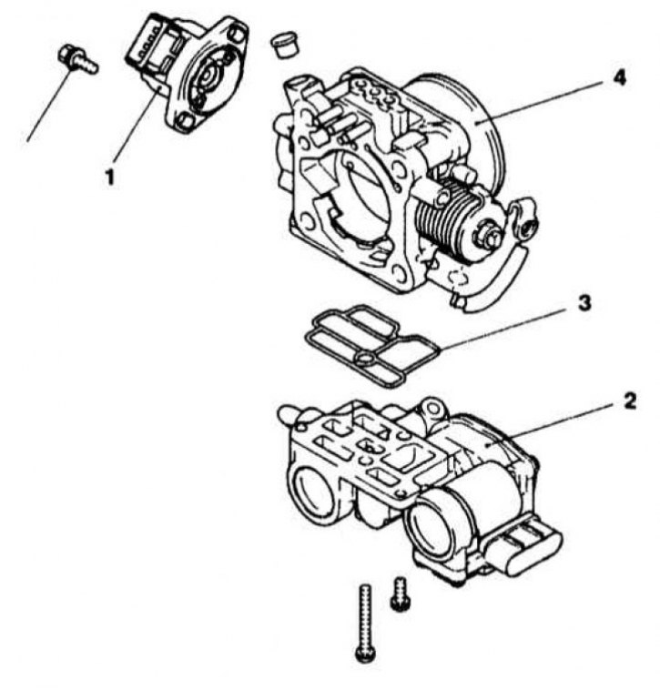
IAC servo motor installation details
1 - TPS (with throttle position sensor switch); 2 - IAC servo motor; 3 - Sealing gasket; 4 - Throttle body
Caution! To avoid damaging the ECM, use only a high impedance (over 10 MΩ) digital voltmeter when performing the following tests!
Note: An OBD-II equipped vehicle should be taken to a service station to have the fault codes read using a special scanner. There are only a few checks (related to identifying the causes of engine failures) that the vehicle owner can perform on their own, in all other cases the vehicle should be taken to a service station.
Oxygen sensors
O2 sensors, or I-probes, monitor the percentage of oxygen in the engine exhaust gases. O2 molecules present in the exhaust system react with the sensor's sensitive element, causing the latter to generate a signal voltage. The signal amplitude, depending on the oxygen concentration, can range from 0 to 1 V, with a signal below 0.4 V indicating a high O2 content - a lean air-fuel mixture, and above 0.6 V - a low O2 content (rich mixture). The ECM continuously monitors the signal coming from the oxygen sensor and, based on the incoming data, makes the appropriate adjustments to the air-fuel ratio, trying to maintain it at an optimal level (14.7 parts air to 1 part fuel - the stoichiometric number), which corresponds to an oxygen sensor reading of 0.4÷0.6 V. The mixture composition is adjusted by controlling the duration of the injection injector opening time. The oxygen sensor begins to generate a signal voltage only after it has warmed up to normal operating temperature, which is approximately 320°C. In view of the above, during the engine warm-up process, the ECM operates in open loop mode.
Models equipped with the OBD-II on-board diagnostics system usually have two oxygen sensors, one of which is installed in front of the catalytic converter, the other - behind, which allows the control module to maintain the efficiency of the catalyst at the maximum level. To speed up the sensors' entry into operating mode, they can be equipped with electric heating elements.
Examination
Attention! Connecting the scanner by piercing the insulation of the wires may damage the electrical wiring - insert the measuring probes into the terminals on the back side of the connector!
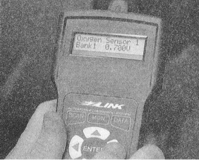
1. Do not forget to check the serviceability of all oxygen sensors included in the system.
Note: Oxygen sensors are usually difficult to access. Use caution - remember that exhaust system components can remain hot for a long time after the engine has stopped, and pressing wiring harnesses against their surface can destroy their insulation. Try, if possible, to check system components using a special scanner that can detect changes in signal voltage within thousandths of a volt.
2. Disconnect the electrical wiring from the sensor.
3. Measure the resistance between the PWR and GRD terminals of the sensor. If the measurement result differs from the nominal value specified by the regulatory requirements (6 Ohm at a temperature of 20°C), then the heating element of the sensor is faulty and the assembly must be replaced.
4. Restore the original wiring connection and start the engine. Connect a digital voltmeter between the HO2S and SIG RTN (GND) terminals of the sensor connector - if the meter readings do not fluctuate quickly enough or are outside the nominal range (0.01÷1.0 V), replace the sensor.
Removal and installation
1. Disconnect the negative cable from the battery.
Warning! If the car stereo system is equipped with a security code, make sure you have the correct combination to activate the audio system before disconnecting the battery!
2. Jack up the car and place it on supports.
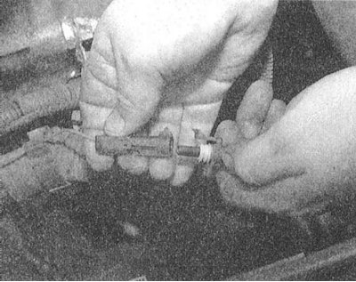
3. Label the wires and disconnect the oxygen sensor from the main engine wiring harness.
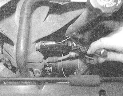
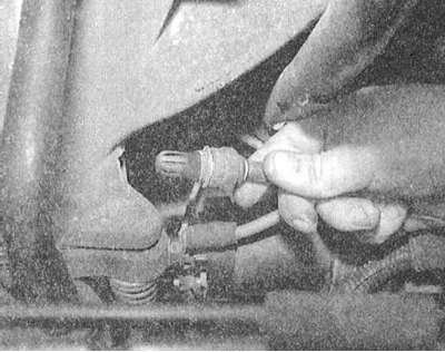
4. Using a special key, unscrew the sensor and remove it from the car.
 |  |
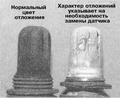 |
5. Assess the condition of the deposits covering the working element of the oxygen sensor.
6. Before installation, the sensor should be lubricated with penetrating oil.
7. Screw the sensor into its standard place and tighten it to the required torque (37÷45 Nm).
8. Restore the original electrical wiring connection.
9. Lower the vehicle to the ground and connect the negative cable to the battery.
Idle Speed Control (IAC) servo motor
The IAC servo drive is implemented on a stepper electric motor with DC power supply. A sensor built into the servo motor assembly continuously monitors the position of the drive and provides the corresponding information to the PCM, which carries out overall control of the idle speed stabilization system.
Examination
1. Place a stethoscope or large screwdriver against the IAC servo assembly. Have an assistant turn the ignition on without starting the engine - the drive motor should make several distinct clicks, confirming that the circuit between the PCM and the system servo is OK. Next, proceed to check the condition of the motor itself.
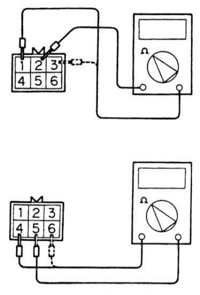
2. Disconnect the wiring from the servomotor assembly and use an ohmmeter to probe terminals 1-2 and 2-3 of the contact connector on the drive side in pairs (not the harness!). If the measurement result is outside the permissible range (28÷33 Ohm), replace the IAC electric motor. If the first test results are positive, probe terminals 5-4 and 5-6 - the result should be within the same range. If the test results are negative, replace the servomotor.
Removal and installation
1. The installation details of IAC servo motor are shown in the illustration.
2. Disconnect the negative cable from the battery.
Warning! If the car stereo system is equipped with a security code, make sure you have the correct combination to activate the audio system before disconnecting the battery!
3. Remove the air cleaner inlet hose.
4. Disconnect the hoses connected to the IAC servo.
5. Remove the mounting bolts and IAC servo assembly from the throttle body.
6. Installation is carried out in the reverse order - do not forget to replace the sealing gasket.
Engine Coolant Temperature (ECT) Sensor
As its name suggests, the ECT sensor measures the engine coolant temperature. The sensor is a thermistor whose resistance changes inversely with the temperature change. The sensor sends the information it reads to the PCM, which uses the data it receives to adjust the ignition timing, EGR flow rate, air-fuel mixture composition, etc. The sensor is connected to two wires that supply a 5 V reference voltage. The sensor's output signal parameters are determined by the change in the working element's resistance, which depends on the temperature.
Examination
1. Drain the engine coolant to below the level of the ECT sensor installed on the intake manifold.
2. Disconnect the electrical wiring from the sensor and remove it from the engine.
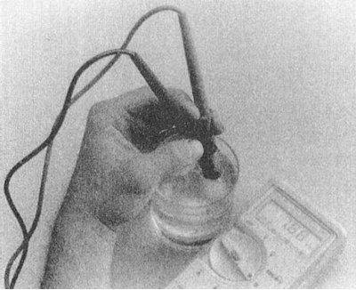
3. Lower the working element of the sensor into a vessel with heated liquid, where the thermometer should also be lowered.
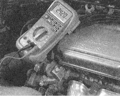
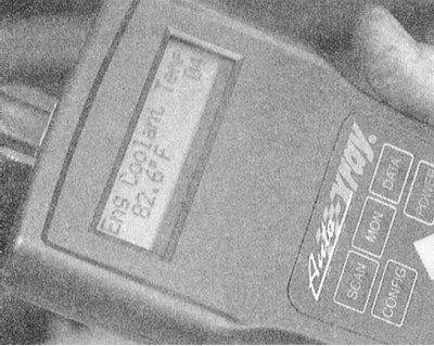
4. Connect an ohmmeter to the sensor and start heating the water, monitoring the nature of the change in the meter readings in accordance with the thermometer readings. Compare the measurement results with the requirements of the Specifications (5.1÷6.5 kOhm at 0°C; 2.1÷2.7 kOhm at 20°C and 0.26÷0.36 kOhm at 80°C. A faulty sensor must be replaced.
Note: Alternatively, the ECT sensor can be tested using a diagnostic scanner.
 |  |
Removal and installation
1. Disconnect the negative cable from the battery.
Warning! If the car stereo system is equipped with a security code, make sure you have the correct combination to activate the audio system before disconnecting the battery!
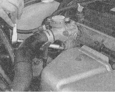
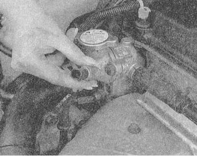
2. Drain the engine coolant until the coolant level is below the position of the ECT sensor installed on the intake manifold.
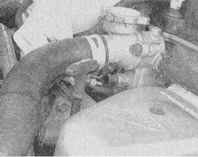
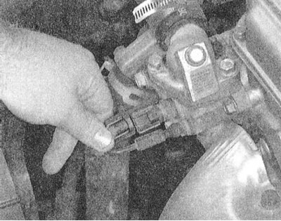
3. Disconnect the electrical wiring from the sensor.
4. Unscrew the sensor and remove it from the engine.
 |  |
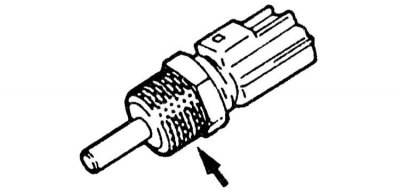 |
5. Before installation, the threaded part of the sensor should be lubricated with a suitable sealant.
6. Screw the sensor into its standard place and tighten it to the required torque (30 Nm).
7. Fill the cooling system with the required amount of the mixture of the required grade (see Chapter Settings and ongoing maintenance).
8. Connect the electrical wiring to the ECT sensor (make sure the connector is securely fastened).
9. Connect the negative cable to the battery.
Intake Air Temperature (IAT) Sensor
The IAT sensor is part of the mass air flow (MAF) sensor and is used to monitor the temperature of the air being sucked into the engine. The sensor, like the ECT sensor discussed above, is a negative temperature coefficient thermistor. The PCM uses the information from the IAT sensor to adjust the ignition timing and air-fuel mixture settings. In addition, this information, in combination with the data from the pressure sensor, is used by the control module to calculate the mass of air being supplied to the engine cylinders. The working signal is generated by the sensor by converting the 5-volt reference voltage in accordance with the change in resistance of the temperature-sensitive element of the assembly.
Examination
1. The IAT sensor is part of the Mass Air Flow (MAF) sensor assembly.
2. Disconnect the electrical wiring from the MAF sensor.
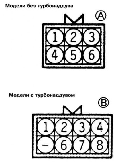
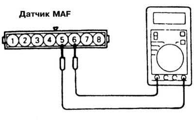
3. Measure the resistance between terminals 4 and 6 (all models except 2.0L DOHC)/6 and 8 (2.0L DOHC models) of the sensor connector.
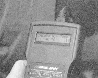
Note: Alternatively, the IAT sensor can be tested using a diagnostic scanner.
 |  |
 |  |
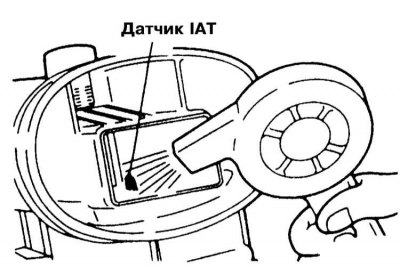 |
4. Compare the measurement results with the requirements of the Specifications (5.3÷6.7 kOhm at 0°C; 2.3÷3.0 kOhm at a temperature of 20°C and 0.30÷0.42 kOhm at a temperature of 80°C).
Note: The sensor can be heated using a household hair dryer.
5. The faulty sensor must be replaced.
Removal and installation
The IAT sensor is part of the MAF sensor, the removal and installation procedures for which are described later in this Section.
Mass Air Flow (MAF) Sensor
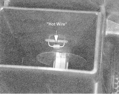
The MAF sensor measures the mass of air flow sucked into the engine. The information provided by the sensor is used by the PCM to determine the duration of the injector opening time. The working element ("hot wire") in the MAF sensor is a thin platinum wire wound on a ceramic blank and filled with glass. The thread is heated to a value exceeding the ambient temperature by 200°C, and the working element is blown by the flow of air sucked into the engine. The working signal, determining the temperature of the sucked air, is taken from the "cold" element of the MAF sensor (IAT sensor).
The reference voltage is supplied to the MAF sensor from the PCM, and grounding is also provided via the control module. The sensor returns a signal to the module, the amplitude of which is proportional to the current flowing through the "hot wire" of the working element and maintaining the temperature of the latter at a given level. Increasing the blowing of the working element leads to a decrease in the resistive resistance of the "hot wire" and a higher current is required to maintain the temperature at the same level. The amplitude of the information pulses of the signal is directly proportional to the strength of the wire flowing through the working element and, if the sensor is functioning properly, should increase with an increase in the flow rate of air sucked into the engine.
Examination
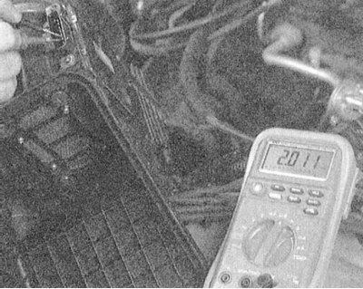
1. Connect a multimeter to the back of the connector terminals and measure the voltage of the MAF sensor.
2. When the ignition is on (do not start the engine), the voltage between the BATT and GND terminals must be at least 10.5 V. If this condition is not met, the condition of the wiring of the power supply and grounding circuits of the sensor should be checked.
3. Now start the engine and measure the voltage between the GND and SIG terminals. If the measurement result is less than 4.5 V, check the condition of the power supply and ground circuit wiring.
4. Without turning off the engine, measure the signal voltage between the GND and SIG RTN terminals. If the measurement result is outside the range of 0.34÷1.96 V, replace the sensor.
Removal and installation
Caution! Avoid exposing the removed MAF sensor to impact, temperature and chemical influences!
1. Disconnect the negative cable from the battery.
Warning! If the car stereo system is equipped with a security code, make sure you have the correct combination to activate the audio system before disconnecting the battery!
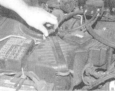
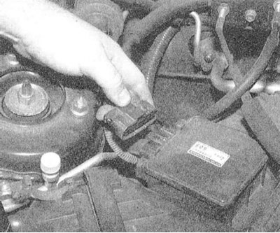
2. Release the air cleaner housing fastening clips.
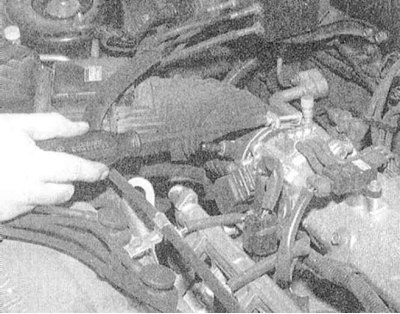
3. Loosen the clamp securing the exhaust air duct to the throttle body.
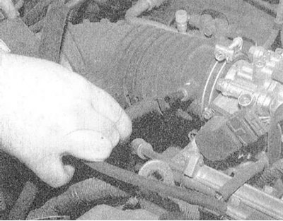
4. Remove the breather hose and disconnect the wiring from the MAF sensor.
 |  |
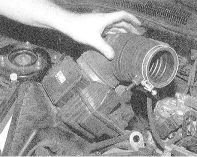 |
5. Remove the air outlet duct, then disconnect it from the air cleaner cover.
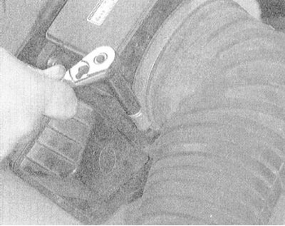 | 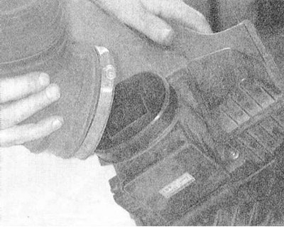 |
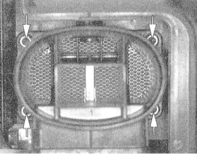
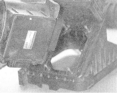
6. Remove the four mounting nuts and remove the MAF sensor assembly from the air cleaner cover.
 |  |
7. Installation is carried out in reverse order.
[The material was created based on the website: mitsubishiman]
Manifold Absolute Pressure (MAP) Sensor
The information received from the MAP sensor is fundamental in the process of controlling the air-fuel mixture composition. Using the temperature and relative pressure data (atmospheric pressure data comes from the BARO sensor) in the intake manifold, the PCM calculates the current flow of air sucked into the engine and, based on the analysis of the received information, determines the required amount of fuel injected into the combustion chambers.
Examination
1. Using a multimeter, check the voltage at the MAP sensor connector (the sensor probes are inserted into the contact terminals on the back of the connector).
2. Turn on the ignition (do not start the engine) and make sure that the voltage between the SIG and GND terminals is at least 48 V, otherwise check the condition of the power supply and grounding circuit wiring, and make the necessary repairs.
3. Start the engine and measure the voltage between the GND and SIG RTN terminals of the connector. If the measurement result is outside the permissible range (0.8÷2.4 V), replace the sensor.
4. If the results of the last check are positive, repeat the measurement, sharply pressing the gas pedal - the reading should rise to 2.4 V and stabilize at this level. The faulty sensor must be replaced.
Removal and installation
1. Disconnect the negative cable from the battery.
Warning! If the car stereo system is equipped with a security code, make sure you have the correct combination to activate the audio system before disconnecting the battery!
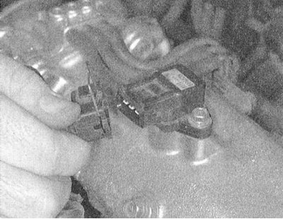
2. Disconnect the electrical wiring from the MAP sensor.
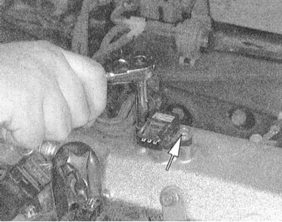
3. Unscrew the sensor mounting bolts and remove it from the intake manifold.
 | 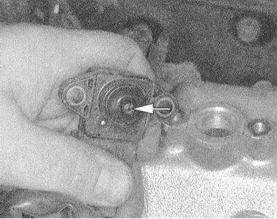 |
4. Installation is carried out in reverse order.
Throttle Position Sensor (TPS)
The throttle position sensor (TPS) is based on a potentiometer, i.e. a resistor whose resistance changes as a result of mechanical movement of moving components. The sensor is mechanically connected to the throttle shaft and generates a signal voltage proportional to the current resistance value of the potentiometer, determined by the position of the valve in the throttle body. The signal from the sensor is sent to the PCM, which, based on an analysis of incoming data, determines the position and direction of movement of the valve and accordingly adjusts the air-fuel mixture, ignition timing and exhaust gas mixture (EGR) intensity.
The control module (PCM) organizes the supply of reference voltage (5 V) and ground to the TPS. The amplitude of the sensor's working signal is determined by the position of the slider of the potentiometer connected to the throttle axis and at idle speed should be about 0.9 V.
Examination
Note: TPS adjustment is not possible, if the sensor is not functioning properly, it must be replaced.
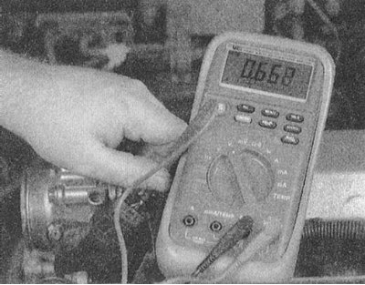
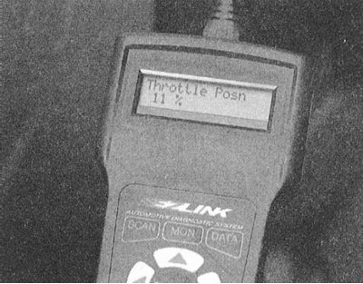
1. Start and use a digital voltmeter to measure the voltage between the SIG RTN and GND terminals on the back of the sensor connector - at idle the readings should be within the range of 0.2÷1.4 V.
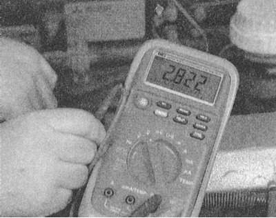
2. Slowly move the throttle valve to the fully open position - the voltage should also slowly increase to 4.8 V.
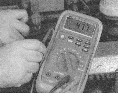
3. If there is no signal, check the reference voltage (5.0 V) and ground potential (less than 0.3 V) to the sensor, and make the appropriate repair to the wiring/replace the PCM if necessary. If the power and ground are normal, replace the sensor.
Note: Alternatively, the TPS can be checked using a scanner-type diagnostic reader.
 |  |
Removal and installation
1. Disconnect the negative cable from the battery.
Warning! If the car stereo system is equipped with a security code, make sure you have the correct combination to activate the audio system before disconnecting the battery!
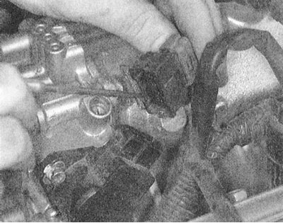
2. Disconnect the wiring from the throttle position sensor.
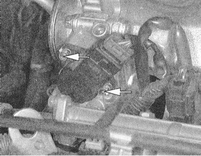
3. Remove the two mounting screws and remove the TPS from the throttle shaft.
4. Installation is carried out in the reverse order - make sure that the sensor is correctly engaged with the valve axis.
Camshaft Position (CMP) Sensor
Based on the analysis of the information received from the CMP sensor, the PCM determines the position of the piston of the first engine cylinder and uses the obtained data when calculating the valve timing. If the CMP signals are missed, the control module injects fuel into the cylinders in accordance with the results of the last successful calculation, which eliminates the possibility of spontaneous engine shutdowns in the event of a CMP sensor failure (the efficiency of the power unit may be significantly reduced).
Examination
The sensor generates an alternating current signal, the frequency of which is proportional to the rotation speed of the engine camshaft. Checking the sensor can only be done using expensive diagnostic equipment, so it would be reasonable to entrust its implementation to specialists of the Mitsubishi car service. Monitoring the operation of the CMP sensor can be done using a scanner-type diagnostic reader - follow the instructions of the device manufacturers.
Removal and installation
Models 1.6L, 2.0L DOHC and 1.8L since 1997.
1. Disconnect the negative cable from the battery.
Warning! If the car stereo system is equipped with a security code, make sure you have the correct combination to activate the audio system before disconnecting the battery!
2. Disconnect the electrical wiring from the sensor and remove the wiring harness mounting bracket from the throttle body.
3. Remove the mounting screws and remove the sensor from the engine.
4. Installation is carried out in the reverse order - ensure that the electrical wiring is laid correctly and that the fasteners are tightened securely.
Models 1.5L, 2.4L, 3.0L SOHC, 3.5L and 1.8L 1993÷1996.
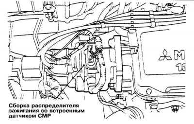
On these models, the CMP sensor is integrated into the ignition distributor. For distributor removal and installation procedures, see Chapter Engine electrical equipment of this Guide.
3.0L DOHC Models
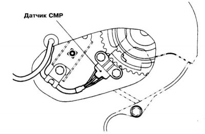
1. CMP sensor installation details on 3.0L DOHC models are shown in the illustration.
2. Disconnect the negative cable from the battery.
Warning! If the car stereo system is equipped with a security code, make sure you have the correct combination to activate the audio system before disconnecting the battery!
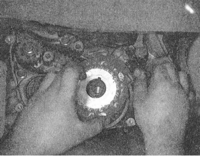
3. Remove the timing belt (see Chapter Engine). Disconnect the wiring from the CMP sensor.
4. Loosen the mounting bolts and remove the CMP sensor from the vehicle.
5. Installation is carried out in reverse order.
Crankshaft Position/Angle Sensor (CKP)
The PCM uses the pulse signals from the CKP sensor to determine the exact piston position of each engine cylinder. Based on the analysis of the information received, the control module determines the optimal injection and ignition times for the fuel.
Examination
As with CMP, the CKP sensor check should be left to a service center. Alternatively, you can use a diagnostic scanner.
Removal and installation
Models 2.0L SOHC and 1.5L 1990÷1996.
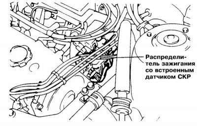
On these models, the CKP is integrated into the distributor assembly, the removal and installation procedures for which are described in Chapter Engine electrical equipment.
1.6L and 2.0L DOHC models
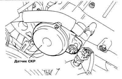
1. The CKP sensor installation details on these models are shown in the accompanying illustration.
2. Disconnect the negative cable from the battery.
Warning! If the car stereo system is equipped with a security code, make sure you have the correct combination to activate the audio system before disconnecting the battery!
3. Disconnect the wiring from the CKP sensor and remove the wiring harness mounting bracket from the throttle body.
4. Remove the mounting screws and remove the sensor from the engine.
5. Installation is carried out in the reverse order - ensure that the electrical wiring is laid correctly and that the fasteners are tightened securely.
Models 1.8 l, 2.4 l, 3.0 l and 3.5 l since 1997.
1. Disconnect the negative cable from the battery.
Warning! If the car stereo system is equipped with a security code, make sure you have the correct combination to activate the audio system before disconnecting the battery!
2. Remove the timing belt (see Chapter Engine).
3. Disconnect the wiring from the CKP sensor.
4. Unscrew the mounting bolts and remove the CKP sensor from the vehicle.
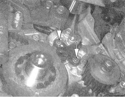 |  |
5. Installation is carried out in reverse order.