Removal and installation
− Before starting to remove the parts, do the following:
- A) Remove the engine crankcase guards.
- b) (GDI engines) Remove the accessory drive belts.
− Removal of parts is carried out in the order of numbers indicated in the figure "Removing the generator assembly".
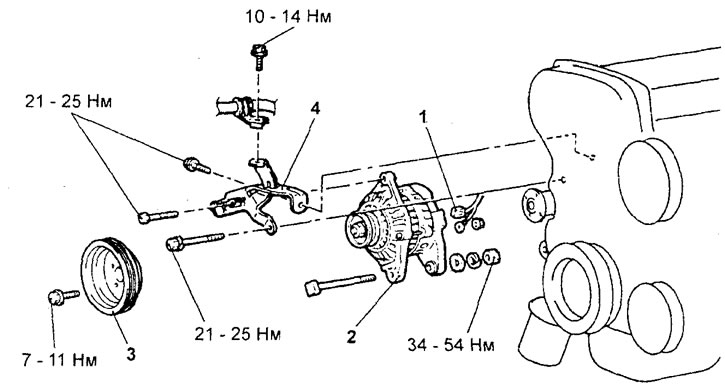
Removing the generator assembly (engine 4G15-GDI). 1 - generator connector, 2 - generator, 3 - coolant pump pulley, 4 - generator adjusting plate.
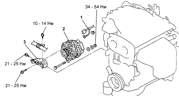
Removing the generator assembly (engine 4G93-GDI). 1 - generator connector, 2 - generator (remove the engine mount), 3 - alternator adjustment bar.
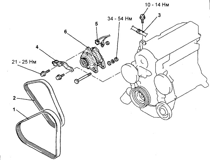
Removing the generator assembly (4G15-MPI engine). 1 - drive belt for the air conditioning compressor and power steering pump, 2 - generator drive belt, 3 - power steering hydraulic hose clamp, 4 - generator adjusting bar, 5 - generator connector, 6 - generator.
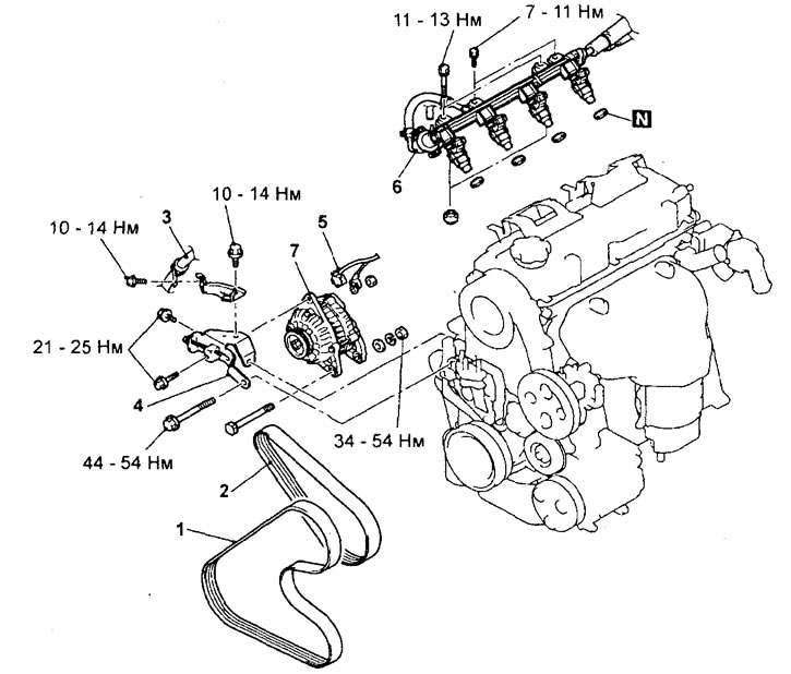
Removing the generator assembly (engine 4G93-MPI). 1 - drive belt for the air conditioning compressor and power steering pump, 2 - generator drive belt, 3 - power steering hydraulic hose clamp, 4 - generator adjusting bar, 5 - generator connector, 6 - fuel manifold assembly with injectors, 7 - generator.
− (Engine 4G93-MPI) When removing parts, pay attention to the following operations.
1. Removing the alternator adjusting plate.
Using a rolling garage jack, slightly raise the engine and remove the alternator adjusting bar mounting bolt.
2. Removing the fuel manifold assembly with injectors.
Attention: be careful when removing the fuel manifold assembly with injectors, do not drop the injectors.
− Installation of parts is carried out in the reverse order of removal.
− After completing the installation of the parts, perform the following operations:
- A) (GDI engines) Install accessory drive belts.
- b) Adjust the tension of the accessory drive belts.
- V) Install the engine crankcase guard.
Disassembly
− Removal of parts is carried out in the order of numbers indicated in the figure "Generator disassembly".
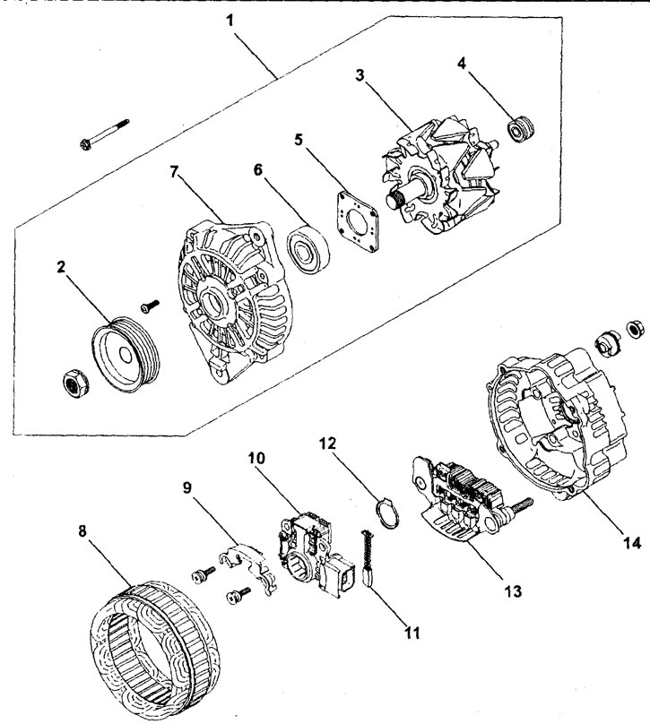
Generator disassembly. 1 - generator front bracket assembly, 2 - generator pulley, 3 - rotor assembly, 4 - rear bearing, 5 - bearing holder, 6 - front bearing, 7 - generator front bracket, 8 - stator, 9 - bar, 10 - voltage regulator and brush holder, 11 - brush assembly, 12 - dust ring, 13 - rectifier unit, 14 - alternator rear bracket.
1. Removing the front bracket and alternator pulley.
A) Turn away bolts.
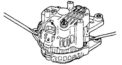
b) Insert a flathead screwdriver between the alternator front bracket and the stator and use the screwdriver as a lever to pry the (down) generator front bracket.
Attention: do not insert the screwdriver too deep, so as not to damage the stator winding.
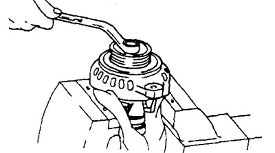
V) Clamp the alternator rotor in a soft-grip vise.
G) Loosen the alternator pulley nut, then remove the pulley and front bracket from the rotor.
Attention: do not damage the rotor.
2. Removing the stator, voltage regulator and brush holder.
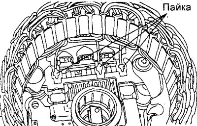
A) Before removing the stator, unsolder the three wires of the stator winding from the main diodes of the rectifier unit.
Attention:
- - Use a soldering iron with a power of 180 to 250 W,
- - When soldering / desoldering contacts, do not hold the soldering iron near the parts for more than 4 seconds.
b) Before disconnecting the rectifier unit from the voltage regulator and brush holder, unsolder the wires of the rectifier unit.
Attention:
- - When soldering/desoldering contacts, be careful that the heat from the soldering iron affects the diodes as little as possible. Perform these operations as quickly as possible.
- - Be careful not to apply excessive force to the diode contacts.
Checking generator parts
1. Rotor check.
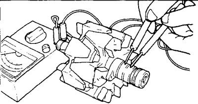
A) Check for an open in the rotor winding.
Check the circuit between slip rings. If there is too little resistance (tends to 0), it means there is a short circuit. In the event of an open circuit in the rotor winding or a short circuit, replace the rotor assembly.
Rated resistance - approximately 3-5 ohms
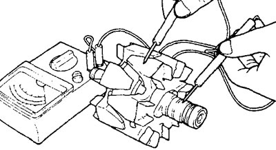
b) Check that the rotor winding is not shorted to "mass".
Check the continuity between slip ring and core. If there is a closed circuit (short circuit "mass") replace the rotor assembly.
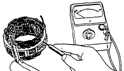
2. Checking the stator.
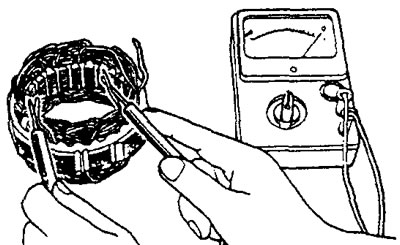
A) Check the stator winding.
Check for an open circuit between the stator winding terminals. If the winding circuit is open (resistance tends to infinity), then replace the stator assembly.
b) Check that the winding is not shorted to "mass".
Using an ohmmeter, check that the stator winding is not shorted to "mass" (that there is no closed circuit between the stator winding and the core). If the resistance tends to zero, then replace the stator assembly.
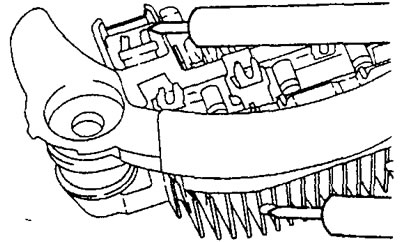
3. Checking the rectifier unit.
A) Checking the positive terminal of the rectifier.
Using an ohmmeter, check that the circuit between the terminal "positive" diodes of the rectifier unit and the output of the stator winding is closed (little resistance). Reverse the polarity of the ohmmeter probes and measure the resistance. If the resistance is small, i.e. the circuit is closed in both directions, then the diode is broken, and the rectifier assembly must be replaced.
b) Checking the negative terminal of the rectifier.
- Using an ohmmeter, check that the circuit between the terminal "negative" diodes of the rectifier unit and the output of the stator winding is closed (little resistance).
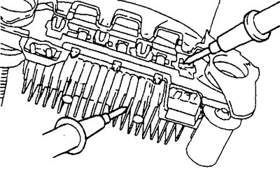
- Reverse the polarity of the ohmmeter probes and measure the resistance. If the resistance is small, i.e. the circuit is closed in both directions, then the diode is broken, and the rectifier assembly must be replaced.
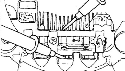
V) Checking three diodes.
Test the three diodes by connecting an ammeter to both leads of each diode and then reversing the polarity of the ammeter connection. If the circuit is closed in both directions for the diode or the circuit is open in both directions, then the diode is faulty and the rectifier unit (heat dissipating block) to be replaced.
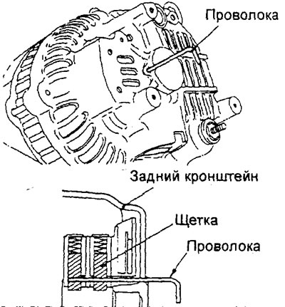
4. Replacement of the generator brush.
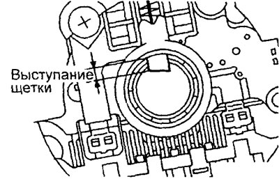
A) If the brush wear has reached the maximum allowable wear line (protrusion of brushes is less than the minimum allowable value), then replace it by following the steps below.
The minimum allowable protrusion of the brushes is 2 mm
b) Unsolder the brush wire and remove the alternator brush along with the spring.
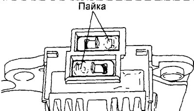
V) To install a new brush, insert it (along with spring) into the brush holder and solder the brush wire so that the brush protrudes as shown.
Assembly
− The generator is assembled in the reverse order of disassembly.
− When installing the parts, pay attention to the installation procedure of the rotor assembly.
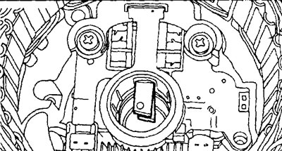
A) Before installing the rotor in the back bracket, press down on the brushes and insert a thin, straight wire into the small hole in the back bracket to hold the brushes up.
b) After installing the rotor, remove the wire holding the brushes.