
Removal and installation
Before you start removing parts, do the following:
- A) Remove the air filter assembly.
- b) Disconnect the variator control cable.
Removal of parts is carried out in the order of the numbers indicated in the figure "Removing the starter".
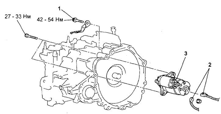
Removing the starter. 1 - CVT bracket bolt, 2 - starter wiring connectors, 3 - starter assembly.
When removing parts, pay attention to the operation to remove the starter.
Support the powertrain assembly from below with a transmission telescopic strut to facilitate removal of the starter mounting bolts.
Installation of details is made in an order, the return to removal.
After completing the installation of the parts, perform the following operations:
- A) Connect the CVT control cable.
- b) Install the air filter assembly.
Disassembly
The starter is disassembled in the order of the numbers shown in the figure "Starter disassembly".
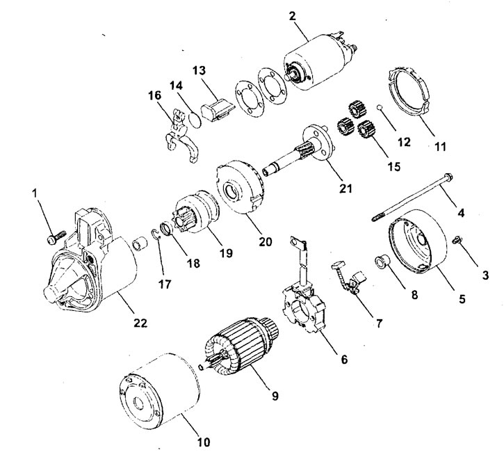
Starter disassembly. 1 - screw, 2 - starter traction relay, 3 - screw, 4 - coupling bolt, 5 - rear cover, 6 - brush holder, 7 - brush, 8 - rear bearing, 9 - starter armature, 10 - starter housing assembly with winding stator, 11 - O-ring "A", 12 - ball, 13 - emphasis "IN", 14 - plate, 15 - planet gear, 16 - starter drive lever, 17 - retaining ring, 18 - restrictive ring, 19 - starter overrunning clutch, 20 - internal gear, 21 - carrier, 22 - front cover.
When removing parts, pay attention to the following operations.
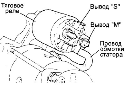
1. Removing the starter traction relay. Disconnect the stator winding wire from the terminal "M" starter relay.
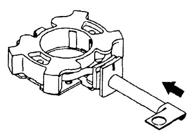
2. Removing the anchor and ball.
Attention: when removing the anchor, do not lose the ball (which is used as a bearing) at the end of the anchor shaft.
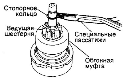
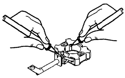
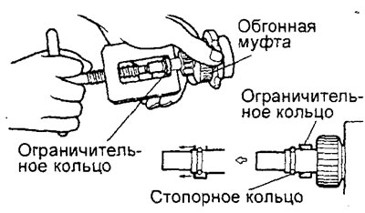
3. Removing the retaining and restrictive rings.
A) Using a suitable socket, tighten (down) stop ring from retaining ring.
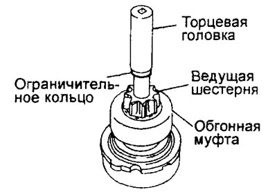
b) Using special pliers, remove the circlip, then remove the restrictor ring and freewheel.
Cleaning starter parts
1. Do not immerse parts in cleaning solutions (solvents). Such washing of the starter housing assembly with the stator and/or armature windings will damage the insulation of the windings. Clean these parts with a cloth only.
2. Do not immerse freewheel assembly with drive gear in cleaning solution (solvent). The freewheel has grease lubricated at the factory and the solvent can remove the grease from the clutch.
3. The overrunning clutch and pinion assembly can be wiped with a brush dampened with cleaning solution and then wiped dry with a cloth.
Starter Parts Check
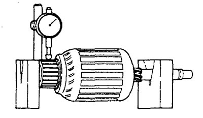
1. Checking the collector.
A) Place the starter anchor on two V-blocks and measure the radial runout of the manifold with a dial gauge.
Nominal value - 0.05 mm
Maximum allowable value - 0.1 mm
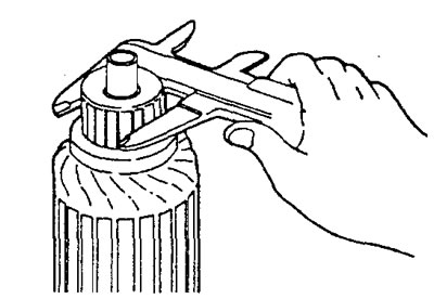
b) Measure the outside diameter of the manifold.
Nominal value - 29.4 mm
Maximum allowable value - 28.8 mm
b) Measure the outside diameter of the manifold.
Nominal value - 29.4 mm
Maximum allowable value - 28.8 mm
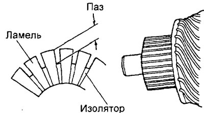
Rated value —— 0.5mm
Maximum allowable value - 0.2 mm
2. Checking the brush holder.
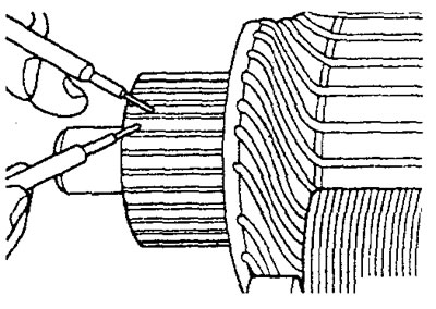
A) Press the brush towards the brush holder as shown in the figure and check that the brush spring is working properly. In the event of a defective brush spring (the brush sinks or the return of the brush to its original position is difficult), replace the brush holder.
b) Check for an open circuit between the plate (a plus) brush holder and brush holder. If the circuit is shorted, replace the brush holder assembly.
3. Checking the overrunning clutch.
A) While holding the freewheel housing with your hand, rotate the pinion gear. The gear should rotate smoothly, without binding, in one direction, and not rotate in the opposite direction. If gear sticks or rotates in both directions, replace freewheel assembly.
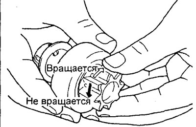
b) Check the drive gear for excessive wear or nicks. If any are found, replace the freewheel assembly. If the drive pinion is damaged, also check the CVT torque converter or automatic transmission ring gear for scoring or excessive wear.
4. Checking the bushings of the front and rear covers of the starter.
Check bushings for excessive wear and tear. If found, replace the front or rear starter cover assembly.
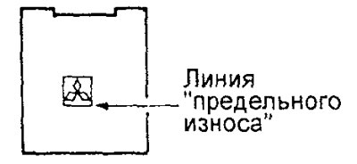
5. Check the condition of the brushes.
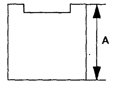
Note: the brushes must be replaced if they are oily or worn so that their edge reaches the line "wear limit" or their length "A" reached the maximum allowable value.
Limit value "A" (MPI engine) - 7.0 mm
GDI engine.
MPI engine
6. Replacement of brushes.
A) To replace the brushes, it is necessary to carefully crush the old brushes with pliers so as not to damage the wires of the brushes.
b) Sand the end of the brush wire with sandpaper to ensure a strong solder.
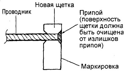
V) Insert the conductor into the hole of the new brush and solder it. At the same time, make sure that the end of the conductor and excess solder do not protrude beyond the surface of the brush.
d) After replacing the brushes or cleaning the brush surfaces, clean the commutator surfaces with sandpaper.
7. Checking the starter anchor.
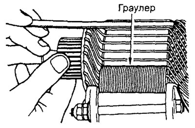
A) Checking the armature winding for a short circuit.
Anchor the trawler (starter and alternator winding tester). While slowly rotating the anchor in the trawler, keep a thin steel plate parallel and just above the anchor. A short-circuited armature winding will cause the plate to vibrate and be attracted to the core. Replace defective anchor.
Caution: Completely clean the surface of the anchor before checking.
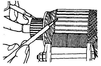
b) Checking the armature winding for a short circuit to "mass".
Using an ohmmeter, measure the resistance between each commutator lamella and the armature core. If resistance tends to infinity (open circuit), then the insulation is good.
V) Check for a break in the armature winding.
Using an ohmmeter, measure the resistance between the collector fins. If there is little resistance (circuit is closed), then the armature winding (insulation) serviceable.
Assembly
The starter is assembled in the reverse order of disassembly.
When assembling, pay attention to the installation operation of the restrictive and retaining rings.
Using a suitable puller, fit the overrunning clutch stop ring onto the circlip.