
Note:
- When operating a car in high mountains (at high altitude) or driving with a cold engine, the ignition timing advances slightly to ensure optimum engine performance. In addition, when knocking occurs, the ignition timing is gradually reduced until knocking stops.
- When the CVT or automatic transmission shifts gears, the ignition timing is reduced to reduce engine torque, thus eliminating vehicle jolts when shifting gears.
The ignition system is non-contact, it has ignition coils with built-in power transistors. The 4G15-MPI and 4G93-MPI engines have one ignition coil for every two cylinders.
The 4G15-GDI and 4G93-GDI engines have a separate ignition coil for each cylinder.
Checks and adjustments
Attention: the test of the power transistor should be carried out quickly (no more than 10 seconds), in order to prevent burnout of the ignition coil winding and failure of the power transistor.
Note: To test the knock sensor (see diagnostic trouble code P0325), crankshaft position sensor and camshaft position sensor, see section "Checking the components of the fuel injection system" in chapter "fuel injection system".
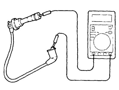
Checking the resistance of high voltage wires (MPI motors)
1. Check each high voltage wire for cracks or damage to the wire insulation and cap.
2. Measure the resistance of each high voltage spark plug wire.
Limit value - max. 22 kOhm
Checking ignition coils and built-in power transistors
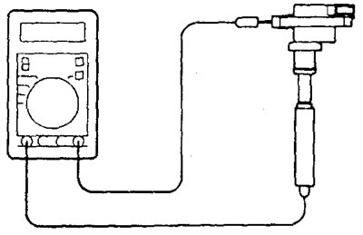
1. (4G15-MPI and 4G93-MPI engines) Measuring the resistance of the secondary winding of the ignition coil.
Measure resistance between leads (for spark plugs) ignition coils for each pair of cylinders (#1 and #4, #2 and #3), as it shown on the picture.
Rated value - 8.5 -11.5 kOhm
2. Checking the power transistor and the primary winding of each ignition coil.
Note: An analog multimeter should be used for testing.
A) Connect the negative lead of the 1.5V power supply to the "2" power transistor.
b) Check the condition of the circuit between the terminals "1" And "2", when output "3" the power transistor and the positive terminal wire of the power supply are connected and disconnected.
Note: connect the probe "minus" multimeter to output "1" power transistor connector.
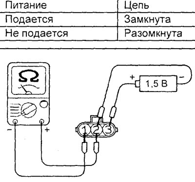
V) Replace the ignition coil if there is a problem.
3. Checking the secondary winding of the ignition coil (Models Without Ignition Fault Sensor).
Note: Performing a resistance test (chains) secondary winding of the ignition coil is impossible, since a diode is integrated into the circuit.
A) Disconnect the ignition coil connector.
b) Remove the ignition coil and install a new spark plug in its high voltage connector.
V) Connect the ignition coil connector.
G) Connect with "weight" spark plug side electrode.
d) Turn the crankshaft of the engine with a starter and check "overshoots" sparks.
e) If spark "does not slip", substitute a known-good ignition coil, then recheck.
and) If with a new ignition coil a spark "slips", then the old ignition coil was faulty. If there is no spark, check the ignition circuits.
Checking the circuits of the windings of the ignition coils using an oscilloscope (MPI motors)
Checking the voltage in the secondary circuit of the ignition coil
1. Standard measurement method.
A) Install the motor tester sensor to measure the secondary voltage on the high voltage spark plug wire for cylinders #2 and #4 or #1 and #3.
Note:
- Maximum secondary voltage impulse (breakdown / sparking voltage) will change its polarity when connecting the motor tester sensor to the spark plug wires of different cylinders.
- Since in this ignition system the formation of a spark occurs simultaneously on the electrodes of two cylinders, secondary voltage pulses appear on the display for each pair of cylinders (cylinders #1-4 and #2-3, respectively). However, only the form of the signal of the secondary voltage of the cylinder to the spark plug wire of which the sensor of the motor-tester is connected is acceptable for observation.
b) Connect the timing sensor of the motor tester to the high voltage spark plug wire.
Note: connect the timing sensor of the motor tester to the spark plug wire of the cylinder to which the sensor of the motor tester is connected to remove secondary voltage signals. In this case, the determination of the secondary voltage signal, which belongs to the tested cylinder, can be difficult. For reference, remember that the secondary voltage signal of the cylinder being tested (to the spark plug wire of which the sensor is connected) will be sustainable.
2. Check that the waveform matches the figure when the engine is running at base idle speed. Pay attention to the following points when observing the signal.
Attention: since the measurements are made using a non-contact type sensor, the measured voltage values will differ from the actual values.
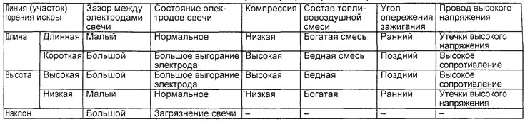
A) Dot "A": The height, length and slope of the spark discharge line indicate the following trends, as shown in the corresponding table (see examples "A", "b", "V" And "G" in point "3").
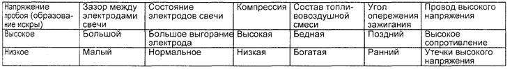
Table. Evaluation of the height, length and slope of the spark line (dot "A").
b) Dot "IN": Number of oscillations in the damped section (see example "d" in point "3"). If the number of oscillations is three or more, then the coil and capacitor are good. If the number of oscillations is less than three, then the coil and capacitor are faulty.
V) Dot "WITH": Number of oscillations at the beginning of the energy storage period (see example "d" in point "3"). If the number of vibrations is 5 - 6 or more, then the ignition coil is good. If the number of oscillations is less than five, then the ignition coil is faulty.
G) Dot "D": Breakdown voltage value (spark generation, cylinder distribution) indicates the following trends, shown in the corresponding table.
Table. Estimation of the breakdown voltage (spark generation, cylinder distribution) (dot "D").
3. Examples of deviations from the normal waveform.
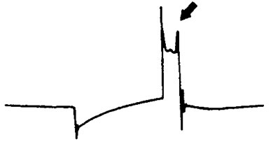
A) Due to the increased gap between the spark plug electrodes, the spark line is high and short.
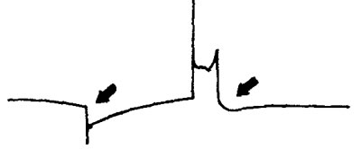
b) Since the gap between the electrodes of the spark plug is too small, the spark line is low, long, and sloping. In addition, there are distortions (fluctuations) in the second half of the spark line section. The cause may be malfunctions in the ignition system: misfires, interruptions in ignition.
V) Due to deposits, contamination on the electrodes and spark plug insulator (abnormal sparking in the gap between the electrodes of the spark plugs) the line of spark burning is low, long, with an inclination. However, there is almost no distortion (fluctuations) this line.
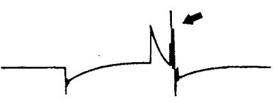
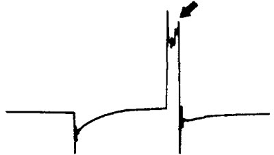
G) Due to poor contact of the high voltage spark plug wire (causes a double spark) the spark line is short and very high.
d) Due to the interturn circuit in the winding of the ignition coil, there are no oscillations in the area of damped oscillations.
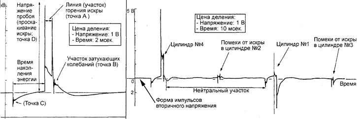
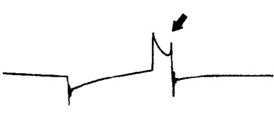
Secondary voltage normal waveform (MPI motors).