



On 16-valve engines, the electronic control unit determines the ignition timing based on sensor signals and generates a spark using two ignition coils.
Electronic ignition systems have ignition voltages of up to 30 kV, and under unfavourable conditions, voltage peaks can break down the insulation.
Models with ignition distributor
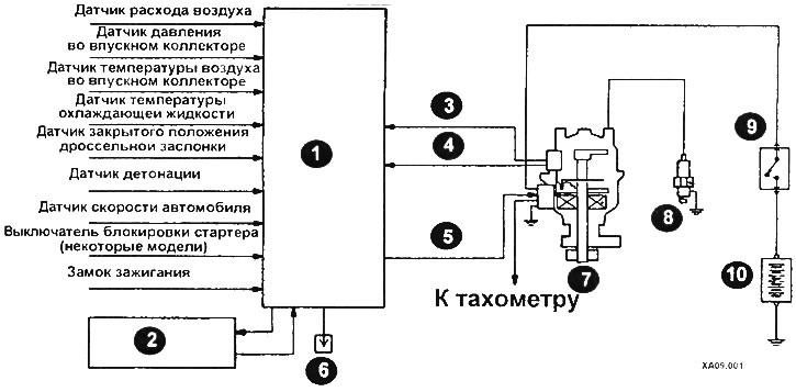
Ignition system diagram for models with distributor ignition
1 - control unit; 2 - automatic transmission control unit; 3 - crankshaft position sensor; 4 - TDC sensor of the first cylinder; 3 - ignition coil; 6 - for adjusting the ignition timing angle; 7 - ignition distributor; 8 - spark plugs; 9 - ignition switch; 10 - battery.
The electronic engine control unit creates and breaks the circuit of the primary winding of the ignition coil, thereby adjusting the ignition timing.
The electronic engine control unit, using the crankshaft position sensor built into the ignition distributor, determines the angular position of the crankshaft and ensures the optimal ignition timing angle depending on the engine operating mode.
When operating the vehicle (at high altitude) or driving on a cold engine, the ignition timing is slightly increased to ensure optimal engine operation.
When detonation occurs, the ignition timing angle is gradually reduced until detonation stops.
When an automatic transmission changes gears, the ignition timing is reduced, eliminating the vehicle's jerking sensation when changing gears.
Models without distributor
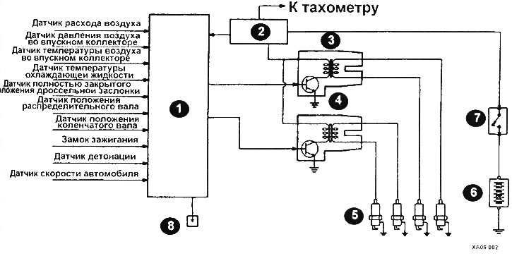
Ignition system diagram for models without a distributor
1 - Engine control unit; 2 - ignition system malfunction sensor; 3 - ignition coil A; 4 - ignition coil B; 5 - spark plugs; 6 - battery; 7 - ignition switch; 8 - for adjusting the ignition timing angle.
This ignition system has two ignition coils (A and B) with built-in power transistors that supply high voltage to the spark plugs of cylinders 1, 4 and 2, 3, respectively.
The interruption of the primary circuit of the ignition coil A winding creates a high voltage in the secondary winding of coil A. The high voltage thus created is supplied to the spark plugs of cylinders No.1 and 4.
The text of the article was taken from the website: www.mitsubishiman.ru
At this point, spark formation occurs simultaneously on the electrodes of both spark plugs. The piston of one of the cylinders is on the compression stroke, and the piston of the other cylinder is on the exhaust stroke. Ignition of the compressed fuel-air mixture occurs only in the cylinder whose piston is at the end of the compression stroke.
Similarly, when the primary winding circuit of ignition coil B is interrupted, high voltage is supplied to the spark plug electrodes of cylinders No.2 and 3.
The electronic engine control unit sequentially switches the spool transistors built into the ignition coils on and off.
The electronic engine control unit, receiving signals from the camshaft position sensor and the crankshaft position sensor, determines which of the ignition coil power transistors to send a control pulse to. The electronic unit, receiving a signal from the crankshaft position sensor, determines the angular position of the latter, determines the optimal ignition advance angle for a given engine operating mode.
The main faults of the ignition system are caused by loose or oxidized contacts, or short circuit to ground of high voltage. Before concluding that any element in the ignition system is faulty, check the condition of the wires or electrical circuits of the ignition system.