
English Русский
Български
Беларускі
Український
Српски
Hrvatski
Română
Polski
Slovenský
Magyar
Articles Bookmark Contacts Sitemap   
Company Audi Company Ford Company Hyundai Company Kia Company Mazda Company Mercedes-Benz Company Nissan
MitsubishiMan.ru


Home Colt Lancer Galant L200 Outlander Pajero Others
Lancer 9 (2000-2007, petrol) Lancer 3 and 5 (1984-1992)

Ignition system — general information (Mitsubishi Lancer 3)

  • Home
  • Lancer
  • 3 (1984-1992)
  • Power unit
  • Ignition system
  • Ignition system — general information
0
The ignition system generates an ignition spark that ignites the air-fuel mixture in the combustion chamber of the corresponding cylinder. To ensure the formation of a powerful ignition spark, the 12 V battery voltage is transformed in the ignition coil into a high voltage of up to 30,000 V.

A diesel engine does not need an ignition system, since with a high compression ratio, the intake air is heated so much that after fuel injection, it ignites on its own.

Depending on the year of manufacture and the type of engine in operation, there are different types of ignition systems:
  • From January 1984 to August 1988: Ignition system with mechanical interrupter or transistor ignition system.
  • From September 1988 to March 1992: Carburetor engines are equipped with a transistor ignition system with mechanical ignition timing adjustment. The 1.5-liter engine with fuel injection is equipped with an electronic ignition system.
  • On 16-valve engines, a crankshaft position sensor is installed instead of a distributor. The electronic control unit calculates the ignition timing based on the sensor signals and in accordance with the characteristic embedded in it, and generates a spark using two ignition coils.

In ignition systems with mechanical regulation, a breaker is installed in the ignition distributor, which has the task of inducing ignition voltage in the ignition coil at the moment the primary winding current is interrupted.

The ignition voltage generated in the ignition coil is supplied via the distributor rotor and the ignition wires to the corresponding spark plug. A spark is generated between the spark plug electrodes, which ignites the air-fuel mixture in the combustion chamber of the cylinder. The ignition timing should be automatically shifted in the ignition advance direction as the engine speed increases. This adjustment of the ignition timing occurs in ignition systems with mechanical regulation in the ignition distributor using inertial weights and vacuum (vacuum hose from the intake pipe to the ignition distributor).


In transistor ignition systems, the ignition spark is generated by a signal from a contactless sensor installed in the ignition distributor. The ignition timing is also adjusted using inertial weights and vacuum.
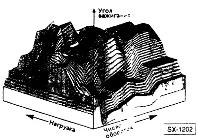


In a 1.5-liter engine with a fuel injection device, the ignition timing is adjusted by a single electronic control unit for the ignition and fuel injection systems. According to the characteristic stored in the unit's memory — see the figure — the control unit sets the optimal ignition timing depending on the engine speed and load. In addition, the computer also controls the ignition process itself. The task of the ignition distributor here is to supply ignition voltage to individual spark plugs in a given sequence.

The original material is here [MITSUBISHIMAN.ru]

16-valve engines have an ignition system without a distributor. The ignition voltage is distributed here by the electronic control unit for the ignition and injection systems. The crankshaft position sensor, driven by the intake camshaft, transmits information about the engine speed and the crankshaft position to the electronic control unit. On engines with a fuel injection device, a knock sensor is installed on the engine block approximately between the 2nd and 3rd cylinders. It registers the occurrence of knock in the engine and notifies the electronic control unit by means of voltage fluctuations about the need to shift the ignition timing in the "late" direction. Shifting the ignition timing prevents knock ignition and thus avoids engine damage.

Caution: When working with the ignition system, safety precautions must be taken.
This article is available at: russian, bulgarian, belarusian, ukrainian, serbian, croatian, romanian, polish, slovak, hungarian
This article was reviewed by: Dmitry Vasiliev
Share with friends:
◀ Previous
Lancer 3 and 5: Ignition system
Next ▶

 
Precautions when working with the ignition system
Ignition distributor — device
Checking the ignition coil
Checking the ignition wires
Replacing breaker contacts
Similar materials for other Mitsubishi models

➤ Ignition system fault diagnostics Mitsubishi Colt 4 and 5 (1991-2003)
➤ Checking the condition and replacing components of the… Mitsubishi Galant 6 and 7 (1987-1998)
➤ Ignition switch Mitsubishi L200 4 (2005-2014, diesel)
➤ Electrical diagram of the ignition system Mitsubishi Outlander 1 (2003-2008)
➤ Design and description of the ignition system Mitsubishi Pajero 1 and 2 (1982-1999)
➤ Scheme 1. Ignition system MPI-SOHC Mitsubishi Carisma (1995-2004)
Link in different formats to this article
Comments and feedback from visitors
No comments yet


Add up two numbers 29 + 14


Lancer 9 (2000-2007, petrol) 
  • General information
  • User manual
  • Maintenance
  • Power unit
  • Repair of MPI engines
  • Repair of GDI engines
  • Engine overhaul
  • Cooling and lubrication system
  • MPI fuel injection system
  • GDI fuel injection system
  • Intake and exhaust system
  • Starting and charging system
  • Transmission
  • Automatic gearbox
  • Variator (CVT)
  • Drive shafts and gearbox
  • Chassis and running gear
  • Front suspension
  • Rear suspension
  • Steering
  • Brake system
  • Body and interior
  • Doors, locks and windows
  • Exterior (external elements)
  • Interior (internal elements)
  • Electrical equipment
  • Heater and air conditioner
  • Security system SRS
  • Equipment and devices
  • Wiring diagrams (saloon)
  • Wiring diagrams (wagon)
Lancer 3 and 5 (1984-1992) 
  • General information
  • Maintenance
  • Power unit
  • Engine repair
  • Lubrication system
  • Cooling system
  • Ignition system
  • Fuel system
  • Carburetor
  • Fuel injection
  • Diesel power system
  • Exhaust system
  • Transmission
  • Clutch
  • Car gearbox
  • Chassis and running gear
  • Front suspension
  • Rear suspension
  • Steering
  • Brake system
  • Wheels and tires
  • Body and interior
  • Exterior (external elements)
  • Interior (internal elements)
  • Heating system
  • Electrical equipment
  • Equipment and devices
  • Power devices
  • Electrical circuits
MitsubishiMan.ru © 2018–2026 • Mobile version • Articles about Mitsubishi • Contacts • Sitemap: EN BG BY UA RS HR RO PL SK HU • Site search • Bookmark
Colt 2 and 3 (1983-1993) · Colt 4 and 5 (1991-2003) · Colt 5 (1995-2003) · Lancer 3 and 5 (1984-1992) · Lancer 9 (2000-2007) · Galant 5 (1983-1989) · Galant 6 and 7 (1987-1998) · L200 4 (2005-2014) · Outlander 1 (2003-2008) · Pajero 1 and 2 (1982-1999) · Pajero 4 (2006-2021) · Carisma (1995-2004) · Space Star (1998-2005) ·
This resource sets cookies 🍪 to avoid bothering you with repeated data entry.