
English Русский
Български
Беларускі
Український
Српски
Hrvatski
Română
Polski
Slovenský
Magyar
Articles Bookmark Contacts Sitemap   
Company Audi Company Ford Company Hyundai Company Kia Company Mazda Company Mercedes-Benz Company Nissan
MitsubishiMan.ru


Home Colt Lancer Galant L200 Outlander Pajero Others
Carisma (1995-2004) Space Star (1998-2005)

Front fog lights (Mitsubishi Carisma)

  • Home
  • Mitsubishi
  • Carisma (1995-2004)
  • Electrical equipment
  • Headlights and lighting
  • Front fog lights
0
Contents: Adjusting the fog lights ⤓ Replacing fog light bulbs ⤓ Removal fog lights ⤓ Checking the Front Fog Light Switch…⤓ Installation ⤓

Adjusting the fog lights
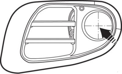


Fig. 19.27. Location of the fog lamp center


1. Measure the center of the fog lights as shown in Fig. 19.27.
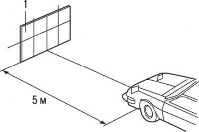


Fig. 19.28. Positioning the vehicle at a distance of 5 m from the screen (1) when adjusting the fog lights


2. Position the vehicle so that the distance from the centres of the fog lights to the screen is 5 m (Fig. 19.28).

3. Bring the tire pressure to the nominal value and leave only the driver in the car or place a load of about 75 kg in his place.

Caution! 4. Set the engine speed to 2000 min⁻¹ and adjust the front fog lights.
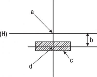


Fig. 19.29. Adjusting the fog lights: H – horizontal line at the level of the center of the headlight; a - center of headlight; b = 100 mm; c – light spot; d – center of brightness of the light spot


The article was taken from the website [mitsubishiman.ru]

5. Check the alignment of the fog light beam on the screen (Fig. 19.29).

Nominal parameters for adjusting the light of fog lights:
  • in the vertical plane - 100 mm below the horizontal line (H);
  • in the horizontal plane – parallel to the direction of vehicle movement.
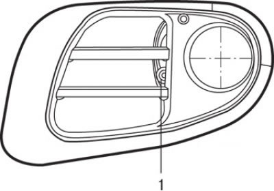


Fig. 19.30. Location of screw (1) for adjusting fog light beam in vertical plane


6. If necessary, make adjustments by turning the adjusting screw (Fig. 19.30).

Attention! Headlights cannot be adjusted horizontally. If the light deviates from the nominal position, check the correct mounting of the headlight or any interference affecting the installation.


Caution: When adjusting, be sure to cover the other headlights.


Replacing fog light bulbs


1. Remove the fog lamp cover.
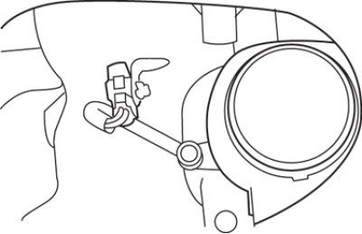


Fig. 19.31. Location of the fog lamp connector


2. Disconnect the connector that is attached to the fog lamp bracket (Fig. 19.31).
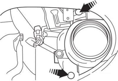


Fig. 19.32. Location of fog light mounting bolts


3. Loosen the bolts and remove the fog lamp assembly (Fig. 19.32).

4. Remove the rear cover of the fog lamp.
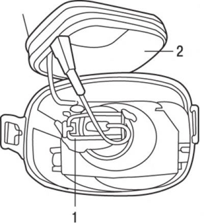


Fig. 19.33. Location of the fog lamp mounting spring: 1 – spring; 2 – rear cover of fog lamp


5. Unfasten the spring securing the lamp and remove it (Fig. 19.33).

Warning! Do not touch the surface of the lamp with your hands or dirty gloves. If the surface of the lamp is dirty, wipe it with alcohol or solvent and dry it thoroughly before installing it in the headlight.


Removal fog lights


To remove, follow these steps.

1. Remove the front bumper.
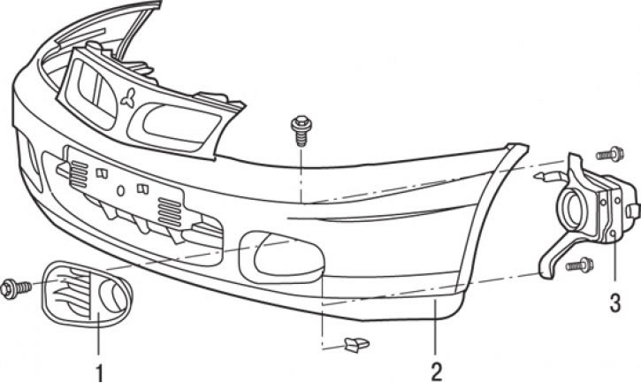


Fig. 19.34. Front fog light: 1 – fog light bezel; 2 – front bumper; 3 – front fog light assembly


2. Loosen the screw and remove the bezel 1 (Fig. 19.34) of the fog light.

3. Loosen the bolts and remove the front fog lamp 3 as an assembly.

Checking the Front Fog Light Switch Circuits


1. Remove the front fog light switch.
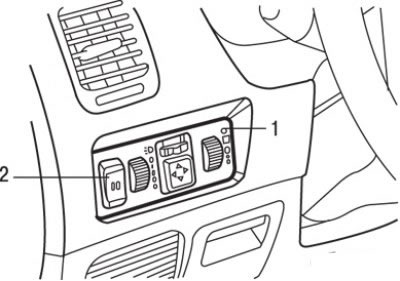


Fig. 19.35. Removing the front fog light switch: 1 – switch casing; 2 – Front fog light switch


2. To remove the front fog light switch, use a screwdriver blade as a lever to remove the switch trim, then disconnect the electrical connector and remove the switch from the trim (Fig. 19.35).

3. To test the switch, you need to use the tester in resistance measurement mode.
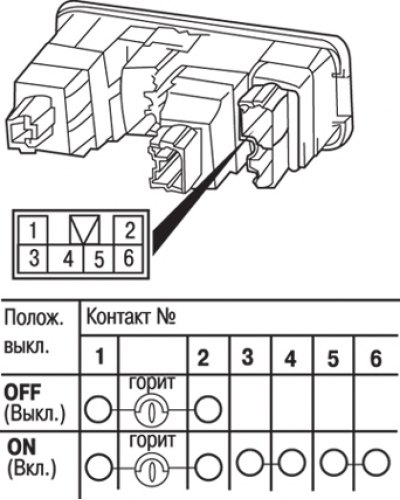


Fig. 19.36. Checking the front fog light switch circuits


4. Disconnect the electrical connector from the switch and measure the state (closed or open) of the electrical circuits between the contacts, which should correspond to those shown in Fig. 19.36. Perform measurements in all switch positions.

5. Check the condition of the switch contacts. If the contacts are oxidized, clean them.

6. If the electrical circuit condition does not correspond to the required one, replace the switch.

Installation


Installation is carried out in the reverse order of removal.
This article is available at: russian, bulgarian, belarusian, ukrainian, serbian, croatian, romanian, polish, slovak, hungarian
This article was reviewed by: Dmitry Vasiliev
Share with friends:
◀ Previous
Carisma: Headlights and lighting
Next ▶

Side direction indicators
Checking switches, switches and relays
Headlights and direction indicators
Replacing lamps
Measuring the brightness of headlights
Rear combination light
Checking the rear fog light switch circuits
High Brake Light — Removal and Installation
Instrument cluster backlight rheostat — removal and installation
Similar materials for other Mitsubishi models

➤ Front fog lights Mitsubishi Colt 4 and 5 (1991-2003)
➤ Front side lights, rear side lights, number plate lights… Mitsubishi Lancer 9 (2000-2007, petrol)
➤ Front seat adjustment Mitsubishi Galant 6 and 7 (1987-1998)
➤ Front fog lights Mitsubishi L200 4 (2005-2014, diesel)
➤ Removal and installation front fog lights Mitsubishi Outlander 1 (2003-2008)
➤ Front fog lights Mitsubishi Pajero 4 (2006-2021)
Link in different formats to this article
Comments and feedback from visitors
No comments yet


Add up two numbers 46 + 48


Carisma (1995-2004) 
  • General information
  • User manual
  • Maintenance
  • Power unit
  • Petrol engines 4G9
  • Diesel engines FBQT
  • Diesel engines F9Q
  • Cooling system
  • Injection system (MPI)
  • Injection system (GDI)
  • Engine electrical equipment
  • Transmission
  • Clutch
  • Mechanical gearbox
  • Automatic gearbox
  • Chassis and running gear
  • Steering
  • Brake system
  • Front suspension and shafts
  • Rear suspension
  • Body and interior
  • Exterior (external elements)
  • Interior (internal elements)
  • Doors, locks and windows
  • Air conditioner
  • Electrical equipment
  • Equipment and devices
  • Headlights and lighting
  • Electrical circuits
Space Star (1998-2005) 
  • General information
  • User manual
  • Maintenance
  • Power unit
  • Petrol engines 4G9
  • Petrol engines 4G1
  • Diesel engines F9Q1
  • Cooling system
  • Fuel injection system GDI
  • Fuel injection system MPI
  • Diesel supply system F9Q1
  • Ignition system
  • Diesel preheating
  • Transmission
  • Clutch
  • Mechanical gearbox
  • Automatic gearbox
  • Chassis and running gear
  • Suspension and drive shafts
  • Brake system
  • Steering
  • Body and interior
  • Exterior (external elements)
  • Interior (internal elements)
  • Doors, locks and windows
  • Heating and air conditioning
  • Electrical equipment
  • Power devices
  • Equipment and devices
MitsubishiMan.ru © 2018–2026 • Mobile version • Articles about Mitsubishi • Contacts • Sitemap: EN BG BY UA RS HR RO PL SK HU • Site search • Bookmark
Colt 2 and 3 (1983-1993) · Colt 4 and 5 (1991-2003) · Colt 5 (1995-2003) · Lancer 3 and 5 (1984-1992) · Lancer 9 (2000-2007) · Galant 5 (1983-1989) · Galant 6 and 7 (1987-1998) · L200 4 (2005-2014) · Outlander 1 (2003-2008) · Pajero 1 and 2 (1982-1999) · Pajero 4 (2006-2021) · Carisma (1995-2004) · Space Star (1998-2005) ·
This resource sets cookies 🍪 to avoid bothering you with repeated data entry.