English Русский
Български
Беларускі
Український
Српски
Hrvatski
Română
Polski
Slovenský
Magyar
Articles Bookmark Contacts Sitemap   
Company Audi Company Ford Company Hyundai Company Kia Company Mazda Company Mercedes-Benz Company Nissan
MitsubishiMan.ru


Home Colt Lancer Galant L200 Outlander Pajero Others
Galant 6 and 7 (1987-1998) Galant 5 (1983-1989, petrol)

Removal and installation the instrument cluster (Mitsubishi Galant 6)

  • Home
  • Galant
  • 6 (1987-1998)
  • Electrical equipment
  • Equipment and devices
  • Removal and installation the instrument cluster
0
Contents: Mirage Models ⤓ Galant Models ⤓ Diamante Models ⤓
Warning! The models of vehicles covered in this manual are equipped with a supplemental restraint system (SRS). Before performing any work near the air bag unit, steering column or instrument panel, turn off the SRS to avoid injury from accidental deployment (see Section Supplemental Restraint System (SRS) - General Information and Precautions). The SRS circuit wiring is easily identified by the yellow color of the insulation.


Mirage Models


Removal


1. Disconnect the negative cable from the battery.

Warning! If the car stereo system is equipped with a security code, make sure you have the correct combination to activate the audio system before disconnecting the battery!


2. Remove the center section of the instrument panel trim.

3. Remove the knee support.

4. Remove the instrument panel trim.

5. Remove the instrument cluster and remove the gauges/indicator lamps that need replacing (see Section Replacing the instrument cluster meters).

Note: When removing the speedometer on cable-driven models, the cable attachment is disconnected from the meter by turning it to the right or left.


Installation


1. Installation is carried out in the reverse order - try not to damage the printed circuit board and instrument cluster meters.

2. Finally, connect the negative cable to the battery and check that all instrument cluster gauges are functioning properly.

Galant Models


Removal


1. Disconnect the negative cable from the battery.


Warning! If the car stereo system is equipped with a security code, make sure you have the correct combination to activate the audio system before disconnecting the battery!


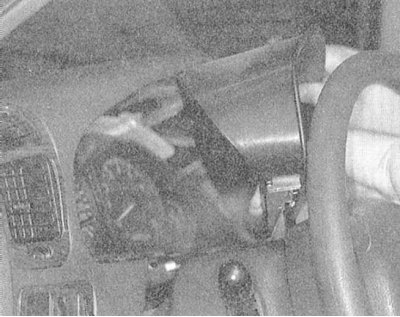
2. Remove the two mounting screws and carefully remove the combination visor from the instrument panel.
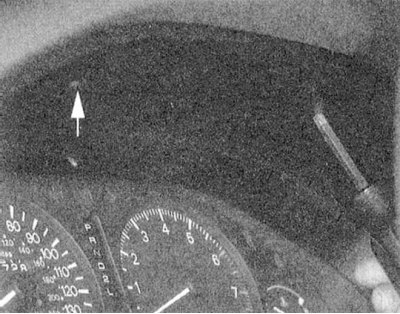


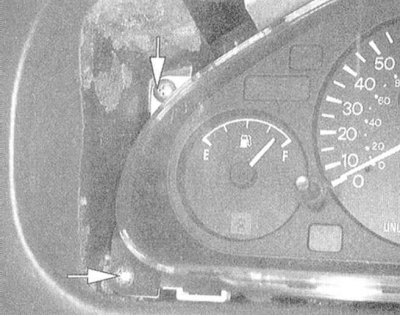
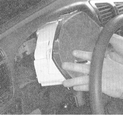
3. Remove the four mounting screws and remove the instrument cluster assembly with the trim.

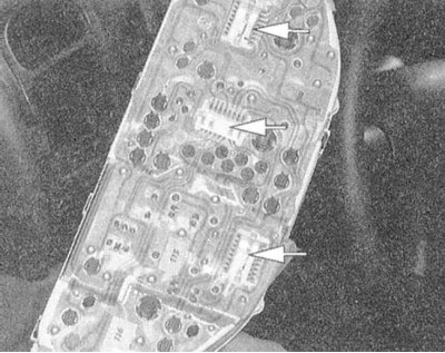
Please note: On some models there is no need to disconnect the wiring harness - the printed circuit board is equipped with pin connectors that are automatically connected when it is installed.
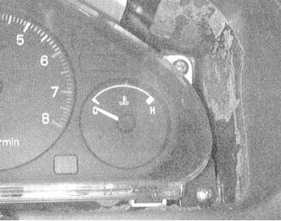


4. Remove the trim and remove the gauges/indicator lamps that need replacing (see Section Replacing the instrument cluster meters).


Note: When removing the speedometer on cable-driven models, the cable attachment is disconnected from the meter by turning it to the right or left.


Installation


1. Installation is carried out in the reverse order - try not to damage the printed circuit board and instrument cluster meters.

2. Finally, connect the negative cable to the battery and check that all instrument cluster gauges are functioning properly.

Diamante Models


Removal


1. Disconnect the negative cable from the battery.

Warning! If the car stereo system is equipped with a security code, make sure you have the correct combination to activate the audio system before disconnecting the battery!


2. Remove the switches and the hood release handle from the knee rest located under the steering column. Unscrew the exposed screws and remove the rest.

3. Remove the upper and lower sections of the steering column cover.

4. Remove the instrument panel trim.

5. Remove the instrument cluster and remove the gauges/indicator lamps that need replacing (see Section Replacing the instrument cluster meters).

Note: When removing the speedometer on cable-driven models, the cable attachment is disconnected from the meter by turning it to the right or left.


Installation


1. Installation is carried out in the reverse order - try not to damage the printed circuit board and instrument cluster meters.

2. Finally, connect the negative cable to the battery and check that all instrument cluster gauges are functioning properly.
This article is available at: russian, bulgarian, belarusian, ukrainian, serbian, croatian, romanian, polish, slovak, hungarian
This article was reviewed by: Dmitry Vasiliev
Share with friends:
◀ Previous
Galant 6 and 7: Equipment and devices
Next ▶

Replacement of lamps in lighting fixtures
Adjusting the direction of the optical axes of the headlights
Removal and installation of sealed headlights
Removal and installation switches
Checking and replacing the turn signal/hazard warning flasher
Replacing the instrument cluster meters
Speed control system (tempostat) — information and diagnostics
Supplemental Restraint System (SRS) — Information and Precautions
Removal and installation a radio/CD player
Removal and installation a CD changer
Similar materials for other Mitsubishi models

➤ Instrument cluster — removal and installation Mitsubishi Colt 2 and 3 (1983-1993)
➤ Instrument cluster indicators Mitsubishi Lancer 9 (2000-2007, petrol)
➤ Instrument cluster Mitsubishi L200 4 (2005-2014, diesel)
➤ Instrument cluster backlight adjustment rheostat Mitsubishi Outlander 1 (2003-2008)
➤ Instrument cluster and gauges Mitsubishi Pajero 1 and 2 (1982-1999)
➤ Instrument cluster illumination adjustment rheostat Mitsubishi Carisma (1995-2004)
Link in different formats to this article
Comments and feedback from visitors
No comments yet


Add up two numbers 13 + 42


Galant 6 and 7 (1987-1998) 
  • General information
  • Introduction to guide
  • User manual
  • Driving and operation
  • Maintenance
  • Power unit
  • Dismantling the engine
  • Engine overhaul
  • Cooling and heating
  • Power and exhaust systems
  • Engine electrical equipment
  • Engine management systems
  • Transmission
  • Mechanical gearbox
  • Automatic gearbox
  • Clutch
  • Drive shafts and transfer case
  • Chassis and running gear
  • Brake system
  • Car suspension
  • Steering
  • Body and interior
  • Exterior (external elements)
  • Interior (internal elements)
  • Doors, locks and windows
  • Electrical equipment
  • Equipment and devices
  • Wiring diagrams Galant
  • Wiring diagrams Mirage
  • Wiring diagrams Diamante
Galant 5 (1983-1989, petrol) 
  • General information
  • Troubleshooting
  • Maintenance
  • Power unit
  • Engine repair
  • Engine overhaul
  • Cooling and heating
  • Fuel and exhaust system
  • Engine electrical equipment
  • Reducing exhaust toxicity
  • Transmission
  • Manual gearbox
  • Automatic gearbox
  • Clutch and drive shafts
  • Chassis and running gear
  • Brake system
  • Car suspension
  • Steering
  • Body and interior
  • Exterior (external elements)
  • Interior (internal elements)
  • Doors, locks and windows
  • Electrical equipment
  • Equipment and devices
  • Electrical diagrams
MitsubishiMan.ru © 2018–2026 • Mobile version • Articles about Mitsubishi • Contacts • Sitemap: EN BG BY UA RS HR RO PL SK HU • Site search • Bookmark
Colt 2 and 3 (1983-1993) · Colt 4 and 5 (1991-2003) · Colt 5 (1995-2003) · Lancer 3 and 5 (1984-1992) · Lancer 9 (2000-2007) · Galant 5 (1983-1989) · Galant 6 and 7 (1987-1998) · L200 4 (2005-2014) · Outlander 1 (2003-2008) · Pajero 1 and 2 (1982-1999) · Pajero 4 (2006-2021) · Carisma (1995-2004) · Space Star (1998-2005) ·
This resource sets cookies 🍪 to avoid bothering you with repeated data entry.