



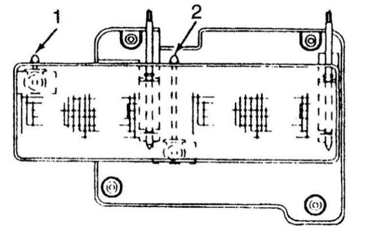
Layout of screws for adjusting the direction of the optical axes of the combined type headlights
1 — Screw for adjusting the headlight position in the vertical plane
2 — Screw for adjusting the headlight position in the horizontal plane
Warning! Failure to properly adjust the direction of the optical axes of the headlights may result in blinding drivers of vehicles moving in parallel and may cause an emergency situation on the road. Checking the correct adjustment of the headlights should be done in a specialized car service workshop!
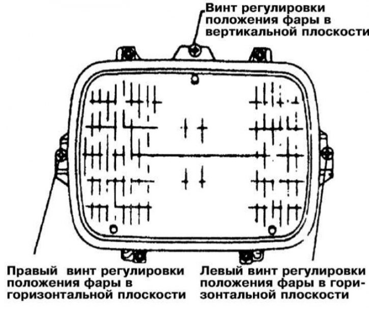
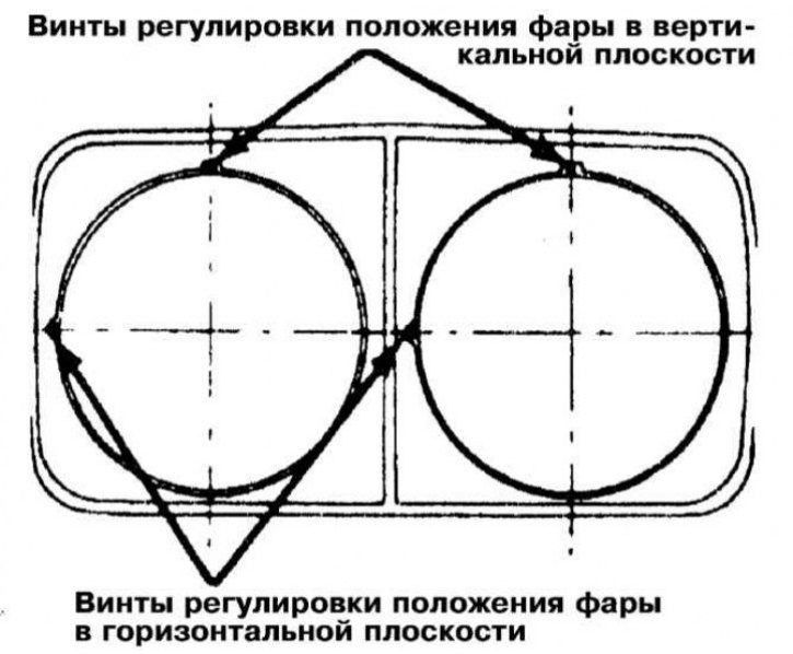
1. The diagram of the location of the headlight adjustment screws is shown in the illustrations.
2. There are several methods for checking the correct adjustment of the direction of the optical axes of the headlights of a car. The simplest of them is described below, which does not require any special skills from the performer and does not require the use of special equipment.
3. Roll the front of the car to the wall. Stick a strip of tape on the wall along a vertical line running in the diametrical plane of the car. Also stick vertical strips of tape along the lines running through the centers of the projections of the headlight lenses on the wall.
4. Stick a horizontal strip of tape onto the wall along a line drawn through the centers of the projections of the headlight lenses onto the wall surface.
Note: This procedure is easier to perform if you drive the car close to the wall.
5. To adjust the direction of the optical axes of the headlights, roll the car away from the wall to a distance of approximately 7.6 m.
Note: The area on which the vehicle is placed must have a flat horizontal surface, preferably with a hard surface. The vehicle's fuel tank must be half full, and all heavy objects that could disrupt the vehicle's alignment must be removed from the passenger compartment and luggage compartment.
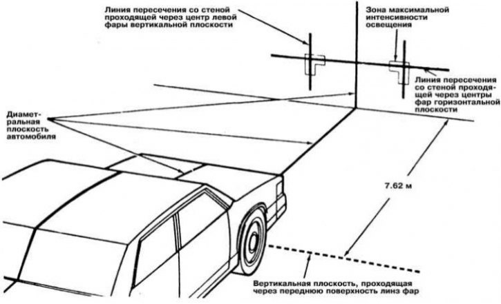
6. Start by adjusting the direction of the low beam optical axis. Try to achieve such a position of the light spots by turning the adjusting screws of the headlights that the zones with maximum illumination intensity are approximately 50 mm below the horizontal line and the same amount to the right of the vertical line.
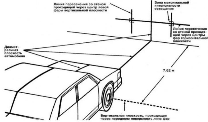
7. After completing the first adjustment, turn on the high beam: the zones of maximum illumination intensity should shift in the direction of the intersection of the vertical lines with the horizontal, ending up slightly below the latter.
Note. It is not possible in practice to achieve the same complete centering of both low and high beams. You should try to achieve some compromise solution taking into account the specifics of vehicle operation, keeping the desire to ensure maximum traffic safety at the forefront.
8. At the earliest opportunity, take the vehicle to a service station to have the optical axes of the headlights adjusted using special equipment.