
Adjustment of the start enable switch
See Section Major overhaul of manual transmission.
Gear shift cable adjustment
1. Adjustment is made on the start enable switch (PNP) find the sensor-switch on the transmission case and make sure that the holes in the lever and the body of the sensor-switch are aligned. Move the selector to position "N", shift the hand lever on the transmission accordingly.
2. Check the correct alignment of the holes in the lever and the body of the sensor-switch, if necessary, make the appropriate adjustment (see below).
3. To adjust, loosen the nut of the cable end and use your hands to take the slack of the latter until the holes are aligned. Tighten the nut.
4. Check up serviceability of functioning of transmission.
Throttle cable adjustment (TV cable)
1. This adjustment is only available on 1996 Mirage models.
2. Move the selector lever to position "N".
3. Loosen the adjusting nut. Slightly pulling on the control cable, tighten the nut with a force of 10÷14 Nm.
4. Make sure the selector lever is still in the "N".
5. Check up serviceability of functioning АТ.
Kickdown Servo Adjustment (F4A20 series transmissions)
1. Thoroughly clean the area around the kickdown servo switch. Remove the snap ring. Remove the sensor switch.
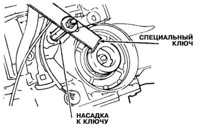
2. Using a special wrench or nozzle, block the actuator piston from turning.
Attention! When dressing the key, the piston should not be pressed down. The nozzle is tightened manually.
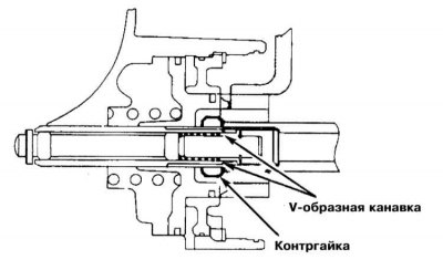
3. Loosen the locknut to the V-groove in the adjusting stem.
4. Screw the inner cap from the Servo Adjustment Kit MD998916 onto the adjusting stem until it stops against the locknut. Place the outer nozzle on the nut.
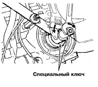
5. Using wrenches, pull both attachments together.
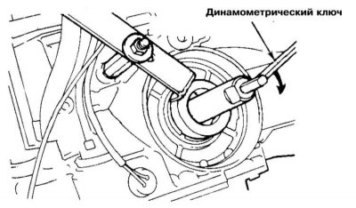
6. Remove the outer nozzle and tighten the inner one with a torque wrench to 10 Nm. Release the key and repeat the procedure for tightening the nozzle to the required torque. Lower the wrench again and tighten the nozzle again, this time to 5 Nm, then loosening it 1/4 turn.
7. Unlock the inner nozzle by loosening it against the lock nut, then turn the nut by hand until it is pressed against the servo piston. Finally, tighten the locknut to the required torque (25÷32 Nm).
Note. Make sure that the stem does not rotate while tightening the nut.
Line pressure regulation
Note. Since the adjustment is made with the valve assembly removed, the pressure should first be measured.
Transmission F3А21
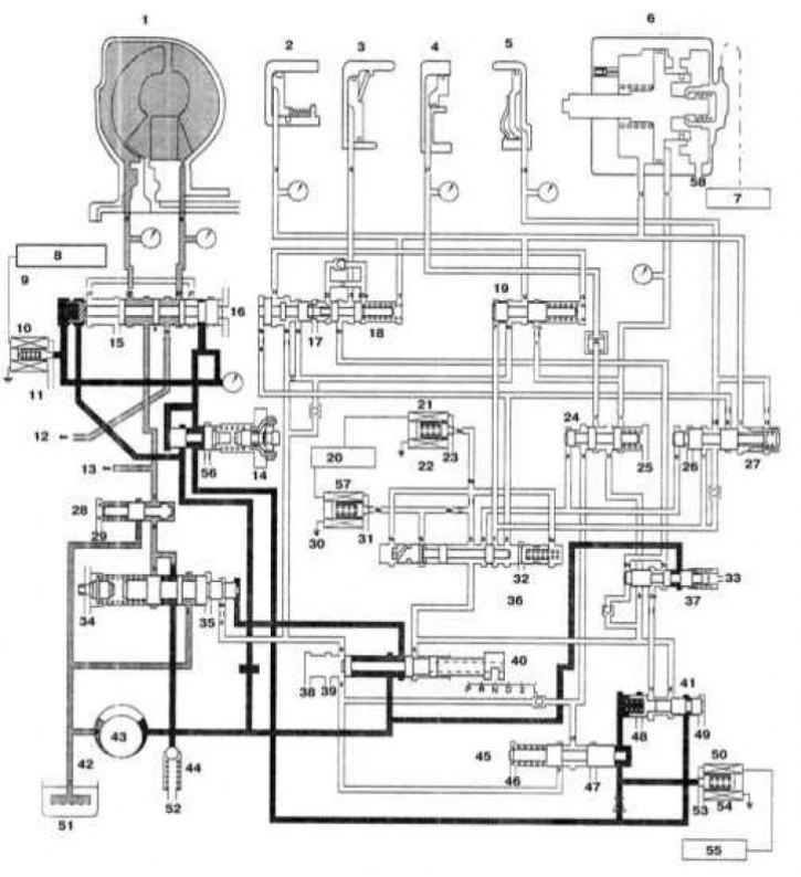
Scheme of pressure distribution in the hydraulic path of 4-speed AT in position "N"
1 - Rotation converter; 2 - Front clutch; 3 - Rear clutch; 4 - Brake assembly of low gears / reverse; 5 - End clutch; 6 - Kickdown mode servo; 7 - Control module three; 8 - Transmission control module; 9 - Damper clutch control valve; 10 - Off; 11 - E / m damper clutch control valve; 12 - To the lubrication system (anterior); 13 - To the lubrication system (rear); 14 - Pressure reducing valve; 15 - Exit.; 16 - Exit.; 17 - Exit.; 18 - The final valve of the rear clutch; 19 - Shift valve 2/3 and 3/4 gears; 20 - Transmission control module; 21 - Solenoid valve A for switching control; 22 - Off; 23 - Exit.; 24 - Switching valve 1/2; 25 - Exit.; 26 - Exit.; 27 - Clutch end valve; 28 - Rotation converter control valve; 29 - Exit.; 30 - Solenoid valve B for switching control; 31 - Exit.; 32 - Exit.; 33 - Exit.; 34 - Regulator valve; 35 - Exit.; 36 - Switch control valve; 37 - N/D switching control valve; 38 - Exit.; 39 - Exit.; 40 - Manual valve; 41 - Pressure control valve; 42 - Oil filter; 43 - Oil pump; 44 - Safety valve; 45 - N/D switching control valve; 46 - Exit.; 47 - Exit.; 48 - Exit.; 49 - Exit.; 50 - E / m pressure control valve; 51 - Oil pan; 52 - Exit.; 53 - Exit.; 54 - Off; 55 - Transmission control module; 56 - Exit.; 57 - On; 58 - Exit.
1. Scheme of hydraulic connections of AT components using the example of a pressure distribution map in position "N" transmissions of the F4A20 series is shown in the illustration.
2. Remove the valve assembly (see Section AT overhaul).
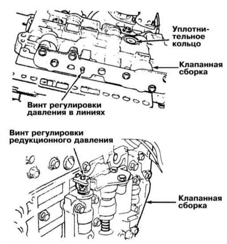
3. Locate the line pressure adjustment screw.
4. Turning the screw on the regulator valve clockwise results in a decrease in pressure in the lines, against - to increase. Turning the screw one full turn results in a pressure change of approximately 26 kPa.
5. After completing the adjustment, reinstall the valve assembly. Fill the transmission with fresh ATF (see chapter Settings and ongoing maintenance) and recheck line pressure. The nominal pressure value in the lines is 360÷420 kPa at idle engine speed and 690÷710 kPa at full throttle.
F4A20 series transmissions (F4A22 and F4A23/33/51)
Adjustment is carried out similarly to that described above for transmissions of the F3A20 series, with the only difference that in this case, turning the adjusting screw one full turn leads to a change in pressure by 38 kPa, and the nominal pressure in the lines is 870÷890 kPa (see specs).
Reducing pressure adjustment (F4A20 series transmissions)
This adjustment is also made on the valve assembly removed from the transmission.