



Contents: Design and operating principle ⤓ Special programs (if provided) ⤓ Planetary gearbox ⤓ The device of the hydraulic part of…⤓ Electrical part of the control…⤓
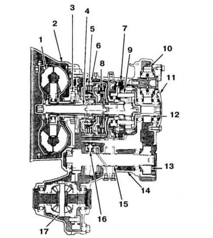
AT F3A21 design
1 - Rotation converter; 2 - Converter housing (dome); 3 - Oil pump; 4 - Primary shaft; 5 - Front clutch; 6 - Kickdown mode activation brake; 7 - Low gear and reverse brake; 8 - Rear clutch; 9 - Planetary assembly; 10 - Transfer case intermediate gear; 11 - Back cover; 12 - Transfer case drive gear; 13 - Transfer case driven gear; 14 - Transmission housing; 15 - Transfer case shaft; 16 - Control regulator; 17 - Differential
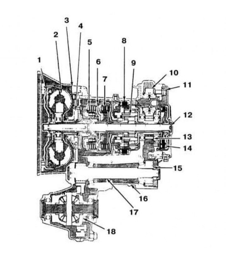
Design of AT series F4A20 (F4A22 and F4A23)
1 - Rotation converter clutch; 2 - Rotation converter; 3 - Converter housing (dome); 4 - Oil pump; 5 - Front clutch; 6 - Kickdown mode activation brake; 7 - Rear clutch; 8 - Low gear and reverse brake; 9 - Planetary assembly; 10 - Transfer case intermediate gear; 11 - Back cover; 12 - Primary shaft; 13 - Transfer case drive gear; 14 - Clutch end sleeve; 15 - Transfer case driven gear; 16 - Transmission housing; 17 - Transfer case shaft; 18 - Differential
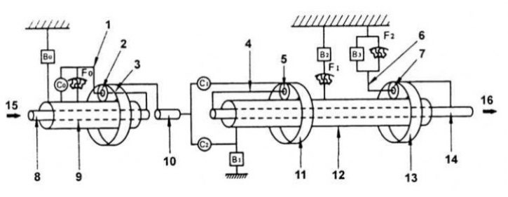
Planetary gearbox operation diagram
1 - Planetary gear carrier; 2 - Satellite of the step-up planetary gear set; 3 - Epicycle of the step-up planetary gear row; 4 - Front planetary gear carrier; 5 - Front planetary gear satellite; 6 - Rear planetary gear carrier; 7 - Rear planetary gear satellite; 8 - Input shaft of the step-up planetary gear set; 9 - Sun gear of the step-up planetary gear set; 10 - Input shaft; 11 - Epicycle of the front planetary row; 12 - Sun gears of the front and rear planetary rows; 13 - Epicycle of the rear planetary row; 14 - Output shaft
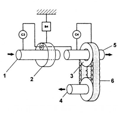
Planetary transfer case operation diagram
1 - Gearbox output shaft; 2 - Epicycle; 3 - Leading sprocket; 4 - Front wheel drive shaft; 5 - Rear wheel drive shaft; 6 - Drive chain
The models considered in this Manual are equipped with 4-speed AT series F3A20 (F3A21) and F4A20 (F4A22, F4A23, F4A33 and F4A51). All transmissions are equipped with a locking rotation converter. The converter provides direct coupling between the engine and the drive wheels of the car. Transmissions can have electronic control - in this case, the on-board processor switches the box to an upshift or downshift based on the analysis of information coming from three electromagnetic units installed on the valve assembly housing.
Due to the complexity of the AT design, the lack of commercially available replacement internal components, and the need to use special equipment, the authors of this Manual do not recommend that vehicle owners perform major transmission repairs on their own. This Chapter only covers procedures for diagnosing common AT failures, its ongoing maintenance, basic adjustments, removal, and installation.
Sometimes, in case of a serious breakdown, it is wiser and easier to replace the transmission than to spend time and money on restoring the failed assembly. Regardless of the chosen method of putting the failed AT into operation, performing its removal and installation yourself will help to significantly reduce costs (first make sure that the transmission really needs restorative repair).
Attention! Towing a vehicle with a failed automatic transmission must be done at a speed of no more than 50 km/h (30 mph) and for a distance of no more than 80 km (50 miles)!
Design and operating principle
In general, an automatic transmission consists of a rotation converter, a transfer case, and a differential. The F3A21 transmission is a 3-speed AT with mechanical control. The F4A20 series has a 4-speed design and electronic control.
The internal structure of the transmissions of both series is almost identical. The main difference is the use of an overdrive 4th gear on the F4A20 series assemblies. The transmission consists of a 3-element rotation converter with a control regulator (F3A20 series), a converter clutch (F4A20 series), one planetary assembly, one brake band and three (F3A20 series) or four (F4A20 series) multi-plate clutches.
The planetary gear assembly consists of two planetary rows. The transfer case includes a planetary row with friction control elements (locking clutch and brake). The operation of the entire transmission is controlled by an electronic unit. Switching between speed modes is performed using a selector lever installed in the car's interior. The selector is connected to the valve assembly by means of a cable, and it can be used to set the range of gears used. In addition to the selector, one or more switches are provided in the interior to set special modes of operation of the transmission.
To prevent breakdowns of the AT due to incorrect selection of the speed range, for example, moving from "D" to "R", a lock is provided on the selector lever - "dangerous" switching can only be done with the lock button pressed. The use of the lock allows you to avoid a situation when one of the ranges of movement can be inadvertently engaged and the car will begin to move uncontrollably. The selector lever can be set to one of six fixed positions: "P", "R", "D", "N", "2" and "L", the purpose of each of which is discussed below.
Position "P"
Selected when parking the car. In this position, all transmission controls are switched off and its output shaft is locked - the car cannot move. The selector should be moved to the "P" position only after the vehicle has come to a complete stop.
Warning! Shifting the selector to position "P" while driving may cause transmission failure!
Position "R"
Reverse. The selector can be moved to the "R" position only after the vehicle has come to a complete stop.
Warning! Engaging reverse gear while the vehicle is moving may cause transmission failure!
Position "N"
Neutral position. All control elements are switched off in the gearbox, which ensures the absence of a rigid kinematic connection between its driving and driven shafts. The output shaft locking mechanism is switched off, i.e. the car can move freely. It is not recommended to switch the transmission to the "N" position when coasting.
Attention! Never turn off the ignition when driving downhill!
Position "D"
Basic driving mode. Provides automatic shifting from first to fourth gear. Recommended for driving in normal conditions.
Position "3"
Driving in the first three gears is permitted. It is recommended to use it when driving on hilly roads or in conditions of frequent stops (heavy urban cycle).
Position "2"
14 Driving is permitted only in first and second gears. Recommended for use, for example, on winding mountain roads. Shifting to third and fourth gears is prohibited. Engine braking is effectively used in this range.
Position "L"
Only first gear is allowed. This range allows for maximum engine braking. It is recommended for driving on steep descents, ascents and off-road.
"OD" mode (F4A20 series transmissions)
The permission to use the fourth, overdrive, gear is carried out using a special button "OD". If the button is in the depressed position and the lever is set to the "D" position, then switching to the overdrive is allowed. Otherwise, engaging the fourth (overdrive) gear is prohibited. The state of the control system in this case is determined by the "O/D OFF" indicator lamp. If the overdrive is permitted, the indicator does not light; if prohibited, it lights. The mode is used when driving at a constant speed on straight sections of the motorway. Avoid using the OD mode in urban conditions, especially in winter, when engine braking becomes vital. Also, do not engage the overdrive mode when the vehicle is fully loaded.
Special programs (if provided)
On cars with automatic transmission, there are two gear shift control modes: "economical" (NORMAL) and "sport" (POWER). The choice is made using a special switch mounted in the central console of the car.
Economy mode (NORMAL)
In this mode, there is a minimum fuel consumption. Gear shifts occur in the middle of the corresponding engine ranges, the nature of the car's movement is calm and smooth.
Sports mode (POWER)
When this mode is switched on, the "ECT POWER" control lamp lights up on the Priora panel. In this mode, maximum engine power is extracted - the gearbox is switched at the upper limit of the corresponding engine speed ranges. The car's throttle response increases significantly, and fuel consumption increases accordingly.
(The original article was published on: mitsubishiman)
Planetary gearbox
The planetary gearbox consists of three planetary gear sets, three locking clutches, four brakes and three freewheel clutches.
Power from the engine is transmitted through the torque converter to the input shaft of the planetary gearbox.
Gear shifting is accomplished by engaging a specific combination of brakes and freewheel clutches, which results in a change in the output shaft speed.
Elements of a planetary gearbox
The functional diagram of the planetary assembly of the automatic transmission is shown in the illustration.
The locking clutch of the step-up planetary gear set (C0) connects both the sun carrier and the sun wheel of the step-up planetary gear set.
The step-up planetary gear brake (B0) stops the step-up planetary gear sun wheel.
Freewheel clutch No.1 (F1) prevents the counterclockwise rotation of the sun gears of the front and rear planetary rows when the second gear brake is engaged.
The forward clutch (C1) connects the input shaft and the front planetary gear epicycle.
The second gear brake (B2) stops the outer ring of the freewheel clutch No.1, thereby prohibiting the counterclockwise rotation of the sun gears of the front and rear planetary rows.
The 1st gear and reverse brake (B3) stops the rear planetary gear carrier.
Freewheel clutch No.2 (F2) prevents the rear planetary gear carrier from rotating counterclockwise.
The direct drive clutch (C2) connects the input shaft and the sun gears of the front and rear planetary gear sets.
The engine braking brake in second gear (B1) stops the rotation of the sun gears of the front and rear planetary gear sets.
The overrunning clutch of the step-up planetary gear set (F0) connects the sun gear and the planet carrier of the step-up planetary gear set when the engine is started.
Planetary transfer case
The diagram of the planetary transfer case operation is shown in the illustration.
The transfer case contains one planetary gear set, two locking clutches and one brake.
Elements of the planetary transfer case:
- The forward clutch (C3) connects the output shaft of the gearbox with the planetary gear satellite of the transfer gearbox.
- The direct drive clutch (C4) connects the rear wheel drive shaft and the leading sprocket of the front wheel drive chain transmission.
- The overdrive clutch (B4) stops the rotation of the planetary gear epicycle of the transfer case.
The device of the hydraulic part of the control system
Transmission
The hydraulic part of the control system consists of an oil pump, valve assembly, electromagnetic valves, clutches and brakes, as well as channels connecting the listed elements. The pressure of the working fluid created by the pump is used to control the friction elements of the transmission, feed the torque converter and lubricate. Three electromagnetic switching valves are installed in the valve assembly. With their help, the electronic unit controls gear shifting and locking the torque converter.
Transfer case
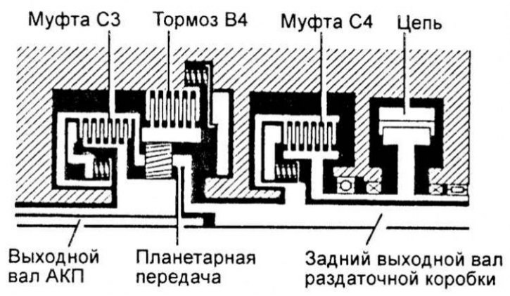
The hydraulic part of the transfer case control system includes: a valve box, electromagnetic valve No.4, a brake (B4), two locking clutches (SZ, S4), and channels connecting the listed elements. The purpose of the box is to control the planetary row, which can be carried out either manually or automatically by an electronic unit.
Electrical part of the control system (F4A20 series transmissions)
The electrical part controls gear shifting in the gearbox and transfer case, as well as the torque converter lockup clutch. It consists of three parts: vehicle speed sensors (VSS), throttle position sensor (TPS) and other information sensors that monitor transmission status parameters and transmit data to the electronic control unit; an electronic control unit that, based on the analysis of the data received, determines the moments of switching in the gearbox and transfer case, and also controls the torque converter lock-up clutch; and an actuator consisting of four electromagnetic valves.