



Automatic transmission | |
General parameters | |
Type AT | 3-speed transmission series F3A21, or 4-speed series F4A20/30/50 |
ATF volume | See Chapter Settings and ongoing maintenance |
Map of clutch and brake band operation | |
Selector lever position | AT trigger elements |
Position "D" | |
| Rear and single-way clutch |
| Rear Clutch and Kickdown Brake Band |
| Front, rear and end* clutches |
| End sleeve clutch and kickdown band |
Position "2" | |
1st gear | Rear and single-way clutch |
2nd gear | Rear Clutch and Kickdown Brake Band |
Position "1" ("L") | |
1st gear | Rear clutch and brake assembly for downshift/reverse |
Position "R" | Front Clutch & Downshift/Reverse Brake Assembly |
Positions "N" and "P" | All elements are disabled or used with minimal efficiency |
Stall test revolutions | |
Transmission | Revolutions, rpm |
3-speed (F3A21) | 1000÷2200 |
4-speed (F4A20/30/50 series) | |
| 2100÷2600 |
| 2500÷3000 |
Tightening forces of threaded connections N·m | |
PNP sensor switch | |
Mirage models up to 1997 and Galant models up to 1993. | 10÷12 |
Mirage models since 1998 and Galant since 1994. | 11 |
Diamante Models | 10÷12 |
Drain plug | 30÷34 |
Filler plug | 30÷34 |
Throttle cable mounting nut | 10÷14 |
Transmission Converter Mounting Bolts | 46÷53 |
Bearing Holder Bolts | 17÷22 |
Rotary converter dome mounting bolts | 19÷23 |
Differential drive pinion mounting bolts | 130÷140 |
Bolts for fastening the drive disk to the rotation converter | 46÷53 |
Bolts for fastening the locking plate of the intermediate gear axle | 47÷58 |
Hand control lever nut | 17÷22 |
Oil pump bolts | 15÷20 |
Fastening the planetary gear holder to the one-way clutch | 35÷45 |
Expander rod stop bolt | 20÷27 |
Transfer case lock nut | 200÷230 |
Clutch end cover mounting bolts | 6÷8 |
Control regulator adjusting screw | 8÷10 |
PNP Switch Sensor Mounting Bolt | 8÷10 |
Hand control lever adjusting screw | 8÷10 |
Oil filter mounting bolts | 5÷7 |
Oil pan mounting bolts | 10÷12 |
Pulse Generator Mounting Bolts | 10÷12 |
Bolt for fastening the reaction shaft support to the oil pump housing | 10÷1 2 |
Valve assembly mounting bolts | 4÷6 |
Bolts securing the valve assembly to the transmission housing | 10÷12 |
Transmission to engine mounting bolts | |
| 75 |
| 43÷55 |
| 48 |
| 43÷55 |
| 48 |
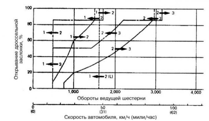
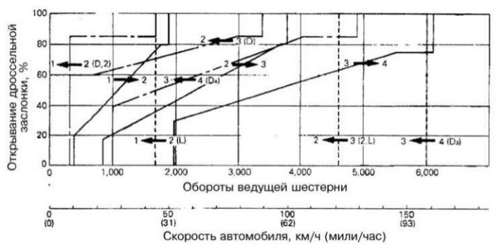
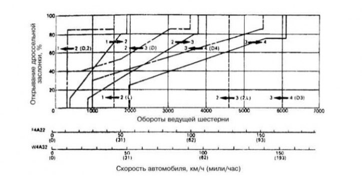
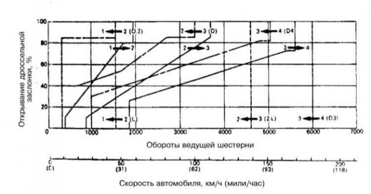
AT switching moments
AT F3A21 (Mirage)
AT F4A20 (Mirage)
AT F4A22 (Galant)
(The original material is here: MitsubishiMan.ru)
AT F4A23 (Galant)
Adjustment parameters
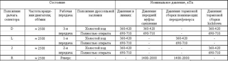
Pressure map for 3-speed transmissions (F3A20 series)
Pressure map for 4-speed transmissions (F3A20/30/50 series)
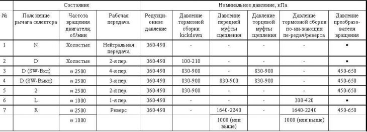
- 10 kPa or lower; · pressure is generated, but not at a standard value; SW overdrive switch
Pressure distribution diagram of the control regulator
