



Contents: List of the most typical AT failures ⤓ Primary checks ⤓ ATF Leak Diagnosis ⤓ Checking the proper functioning of…⤓ Hydraulic checks ⤓ Analysis of line pressure test…⤓ Sea trials ⤓
AT failures most often occur for one of the following five reasons:
- a) Reduced engine output efficiency;
- b) Violation of regulations;
- c) Hydraulic failure;
- d) Mechanical damage;
- e) Failures of the on-board processor/its signal chain.
Failure diagnostics should always start with the most basic checks: assess the level and condition of the ATF (see Chapter Settings and ongoing maintenance), check the adjustment of the gearshift and throttle valve drives. Next, conduct a road test of the car to determine the effectiveness of the corrections made. If the problem cannot be resolved, the car should be taken to a service station for more detailed diagnostics using special equipment. A description of some of the symptoms of AT malfunctions is given in the Section on Diagnostics of Failures of Vehicle Components and Systems at the beginning of this Manual.
List of the most typical AT failures
Note: See also the relevant subsection in the Section on Diagnostics of Failures of Vehicle Components and Systems in the Introduction to this Manual.
The transmission allows the vehicle to move forward or backward
- The adjustment of the shift rods is broken;
- The ATF level has dropped/the hydraulic pressure is low due to a blocked oil filter, incorrect installation of the valve assembly, or damage to the pressure reducing valve/rotation converter control valve.
There is no movement in positions "D" and "2"
- The front clutch is faulty.
Forward gears do not work
- Rear clutch is faulty;
- The "ND" accumulator valve is faulty.
Engine stalls when shifting transmission from "N" to "D" or "R"
- The engine does not develop the required power;
- The AT valve assembly is installed incorrectly;
- The valve assembly check ball is jammed;
- The rotation converter clutch valve or the "ND" accumulator valve is faulty.
The box slips when moving forward
- ATF level/hydraulic pressure dropped;
- The one-way clutch is faulty;
- The valve assembly is faulty;
- The rear clutch is excessively worn.
The gearbox slips when reverse is engaged
- ATF level/hydraulic pressure dropped;
- Low/reverse brake circuit faulty;
- The front clutch is excessively worn;
- The valve assembly is faulty.
There is too weak reception of the car when driving in 2nd and 3rd gears
- ATF level/hydraulic pressure dropped;
- The rotation converter is faulty;
- Rear clutch is faulty;
- Valve assembly is faulty/incorrectly installed;
- The kickdown mode activation brake assembly is faulty;
- The kickdown mode servo adjustment is broken.
Reduced engine braking performance in mode "L"
- The valve assembly is faulty;
- The low/reverse brake assembly is faulty.
The stop speed of the rotation converter is too low
- Insufficient engine power;
- The rotation converter is faulty.
The stop speed of the rotation converter is excessively high
- ATF level/hydraulic pressure dropped;
- The one-way clutch is faulty;
- Front clutch is faulty;
- Rear clutch is faulty;
- The valve assembly is faulty.
The vehicle is moving with the transmission in position "N"
- The front or rear clutch is faulty.
Transmission does not shift into park position
- The shift drive adjustment is out of order;
- The mechanism for engaging the "P" position is faulty.
There is a discrepancy between the modes selected and those actually activated
- ATF level/hydraulic pressure dropped;
- The valve assembly is faulty;
- Front clutch is faulty;
- The kickdown mode activation brake band is faulty;
- Kickdown servo adjustment is out of adjustment;
- The control regulator is faulty.
The transmission does not downshift in any position
- The throttle valve is not functioning properly;
- 1/2 gear shift valve is faulty;
- 2/3 gear shift valve is faulty;
- The control regulator is faulty.
The transmission shifting from 1st to 2nd gear is faulty
- ATF level/hydraulic pressure dropped;
- The oil filter is clogged;
- The kickdown mode brake band is faulty;
- Kickdown servo adjustment is out of adjustment;
- Front clutch is faulty;
- The control regulator is faulty;
- The valve assembly is faulty.
The transmission shifting from 2nd to 3rd gear is faulty
- ATF level/hydraulic pressure dropped;
- The oil filter is clogged;
- The kickdown mode brake band is faulty;
- Kickdown servo adjustment is out of adjustment;
- Front clutch is faulty;
- The control regulator is faulty;
- The valve assembly is faulty.
Shifting from 1st to 2nd and from 2nd to 3rd gear is too abrupt
- Throttle cable adjustment is out of adjustment;
- The valve assembly is faulty;
- The control regulator is faulty;
- Front clutch is faulty;
- The kickdown mode brake band is faulty;
- The kickdown mode servo adjustment is broken.
Shifting from 3rd to 2nd and from 2nd to 1st gear is too abrupt
- The kickdown mode brake band is faulty;
- Kickdown servo adjustment is out of adjustment;
- The control regulator is faulty;
- The valve assembly is faulty.
The rotation converter makes a howling sound when operating
- The oil pump is faulty.
The rotation converter rattles when working
- The drive disk cracked;
- The bolt securing the rotation converter to the drive disk has become loose.
Primary checks
1. Warm up the transmission to normal operating temperature by taking it for a short drive.
2. Check the ATF level (see Chapter Settings and ongoing maintenance):
- a) If the fluid is clearly low, make the appropriate adjustment by adding the required amount of fresh ATF. Check the dipstick to make sure the adjustment is correct, then check the transmission for signs of external leaks;
- b) If the level is excessively high, drain the excess ATF, then check it for traces of coolant, indicating a leak in the internal radiator bulkheads separating its heat exchanger from the side ATF tanks;
- c) If the ATF is foamed, drain the transmission and fill it with fresh fluid, - check the drained ATF for traces of coolant.
3. Check the engine idle speed setting (see Chapter Power and exhaust systems). If necessary, take the vehicle to a service station to have the appropriate adjustments made.
Note: If the engine is not in good condition, do not proceed with the initial transmission checks until the appropriate corrections have been made.
4. Make sure that the traction control cable/rod is adjusted correctly and runs smoothly.
ATF Leak Diagnosis
Most leaks are easily identified by visual inspection. Repair usually consists of replacing the affected seal or gasket. If the source of the leak cannot be identified by visual inspection, proceed as described below.
First of all, it is necessary to exclude the possibility of an error in determining the nature of the leak. ATF should not be confused with engine oil or brake fluid (transmission fluid is usually dark red).
To identify the source of the leak, take a short (several kilometers) drive, then park the car over a clean sheet of cardboard. After a couple of minutes, the source of the leak can be identified by traces of liquid dripping onto the cardboard.
Carefully inspect the suspected area and its surrounding surface, paying particular attention to the joints of the mating gasket surfaces. Use a pocket mirror to widen the viewing angle.
If the source of the leak still cannot be identified, thoroughly wipe the surface of the suspected area with a rag soaked in solvent, then dry it.
Take another short drive, this time changing speed frequently, then re-inspect the cleared suspect area.
After identifying the source of the leak, you should determine and eliminate the cause of its development, and only then proceed to perform the necessary restoration work. Replacing a damaged gasket will not lead to the desired result if the defect of the mating surface that led to the failure of the seal is left unrepaired. Thus, a deformed flange must be straightened.
The following subsections list the most common causes of ATF leaks and the conditions that must be met to prevent recurrence.
Note: Some of the listed requirements cannot be met without the use of special equipment. In this case, the car should be taken to a service station.
Leaks through gasket surfaces
1. Periodically inspect the transmission oil pan. Check that the mounting bolts are in place and securely tightened, and make sure that there are no signs of mechanical damage on the cover (sump deformation can lead to failure of the valve assembly located inside the transmission).
2. Possible causes of sump leaks include excessively tight tightening of the mounting bolts, obstruction of the ventilation line, mechanical damage to the sealing surface of the transmission case, destruction of the gasket, as well as the formation of cracks or porosity in the walls of the case. If the sump or transmission case gasket is formed by a sealant cushion, it is possible that the wrong type of the latter was selected. Leaks through the sump gasket can also be caused by overfilling the case with transmission fluid or by an increase in ATF pressure.
Leaks through seals and cuffs
1. The most common causes of transmission seal failure include excessively high ATF level/pressure, obstruction of the ventilation pipe, mechanical damage to the walls of the seat, damage to the seal itself, or improper installation of the latter. It is also possible that the journal of the shaft inserted into the seal is damaged, or that the latter has excessive play due to bearing wear.
2. Check the condition and correct fit of the dipstick guide tube sealing collar. Periodically inspect the area around the speedometer/velocity sensor (VSS) drive gear for signs of leaks. Replace the sealing ring if necessary.
Leaks through defects in the walls of the transmission housing
1. The cause of ATF leaks may be the formation of cracks or pores in the transmission housing - consult with car service specialists.
2. Check the tightness of the ATF cooler hose connection fittings.
Leaks through the breather and filler neck
Leaks through the vent breather or filler neck can occur due to transmission overflow, coolant entering the ATF, breather/vent obstruction, or return drains.
Checking the proper functioning of the mechanical subsystems of the AT
Checking on a fully braked vehicle (stall test)
1. The performance of the transmission and engine is determined by measuring the crankshaft speed in the "R" and "D" positions of the automatic transmission with the vehicle fully braked.
Attention! ATF must be warmed up to normal operating temperature (50÷80°C). The duration of each check should not exceed five seconds. The check should be carried out by two people: one should observe the wheels of the car, the second performs the necessary manipulations in the car interior.
2. Brake the front and rear wheels of the car.
3. Connect a tachometer to the engine.
4. Fully apply the parking brake.
5. With your left foot, press the foot brake pedal all the way down.
6. Move the transfer case control lever to position H2.
7. Start the engine. Move the AT selector lever to the "D" position, press the gas pedal all the way down and quickly read the tachometer readings.
Caution! If during the test the rear wheels of the vehicle start to rotate before the engine speed reaches the required value (2300÷2600 rpm), release the gas pedal and stop the test.
8. Perform a similar check with the transmission in the "R" position.
9. If the engine speed in both cases is the same and lower than required, then the engine does not develop full power, or the freewheel clutch of the torque converter is faulty.
Note: If the frequency is 600 rpm lower than required, the torque converter itself may be faulty.
10. If the engine speed is higher than required in the transmission position "D", this may indicate an excessive drop in pressure in the main line, slippage in the freewheel clutch No.2, malfunction of the freewheel clutch of the overdrive planetary gear set, or slippage in the direct drive clutch of the transfer case.
11. Exceeding the engine speed in the "R" position of the transmission indicates a drop in pressure in the main line, slippage in the direct drive clutch, slippage in the brake of the first and reverse gears, malfunction of the freewheel clutch of the overdrive planetary gear set, or slippage in the direct drive clutch of the transfer case.
12. If the engine speed is too high in both transmission positions, this means that either the pressure in the main line has dropped excessively, or the ATF level does not correspond to the required value, or the freewheel clutch of the overdrive planetary gear is not functioning properly, or there is slippage in the direct drive clutch of the transfer case.
Checking the switching delay time
1. If, with the engine idling, you move the selector lever to one of the forward ranges, some time must pass before the start of movement. The duration of this delay can be used to judge the proper functioning of the locking clutches of the overdrive planetary row, forward gear, direct gear, and brake of first and reverse gears.
Attention! The test should be performed on an engine warmed up to normal operating temperature. The final result should be obtained by averaging the results of three tests, with at least one minute between each. Below is a detailed description of the procedure for performing this test.
2. Fully set the parking brake. Move the transfer case control lever to position H2.
3. Start the engine and check its idle speed - make the appropriate adjustments if necessary.
4. Move the selector lever from position "N" to position "D" and measure the delay time using a stopwatch - the average value of three consecutive measurements should not exceed 1.2 seconds.
5. Proceeding in a similar manner, determine the delay time for engaging reverse gear, which should not exceed 1.5 seconds.
6. The reason for the excessive delay in engagement may be too low pressure in the main line, malfunction of the forward clutch, freewheel clutch of the planetary gear assembly, or brake of the first and reverse gears.
Hydraulic checks
Note: You will need an assistant to perform the tests described below.
1. Check the ATF level and condition (see Chapter Settings and ongoing maintenance).
2. Warm up the transmission to normal operating temperature by taking it for a short drive.
3. Jack up the car and place it on supports - the drive wheels should be completely off the ground.
4. Connect the tachometer according to the instrument manufacturer's instructions. Position the tachometer so that its indicator is clearly visible from the driver's seat.
5. Find the pressure gauge connection fittings on the side walls of the transmission housing, near the line where it joins the oil pan. Unscrew the plug and connect the gauge adapter to the corresponding fitting.
Note: For some measurements you will need a pressure gauge with a scale of up to 28 kgf/cm² (see Specifications).
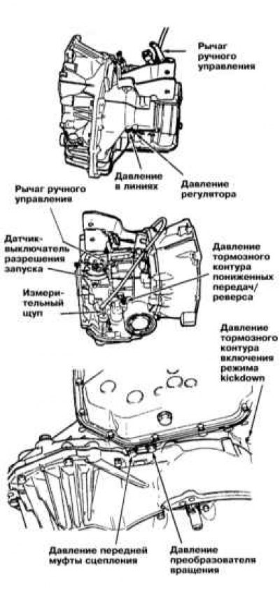 | 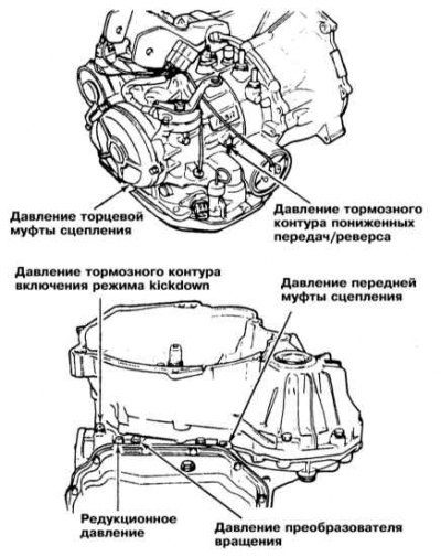 |
6. Measure the hydraulic pressure of the AT at different engine speeds and in different selector lever positions. Compare the measurement results with the requirements of the Specifications. If necessary, make the appropriate adjustments, replace defective components.
7. After completing the measurements, tighten the nipple plugs to the required force.
The original article is on mitsubishiman.ru
Analysis of line pressure test results
Transmission F3A21
1. Excessively low pressure in positions "D", "L" and "2" with normal readings in position "R" indicates the presence of leaks in the rear clutch circuit, or through the accumulator sealing ring 1-2.
2. Low pressure in positions "D" and "R" with normal pressure in position "L" indicates leaks in the front clutch circuit.
3. Low pressure in positions "D" and "L" with normal pressure in position "2" is evidence of leaks in the low gear/reverse circuit.
4. Low pressure in all modes may indicate a faulty oil pump, loose valve assembly mounting bolts, a blocked filter, or a jammed pressure regulator valve.
Transmissions of the F4A20 series (F4A22 and F4A23/33/51)
1. The reasons for the pressure decrease/increase in all lines may be: obstruction of the oil filter, violation of the control regulator settings, jamming of the pressure regulator valve, incorrect oil pump discharge pressure, ATF leaks in the valve assembly.
2. Incorrect pressure relief may indicate a blockage in the pressure relief filter, jamming of the pressure relief valve, or development of leaks in the valve assembly.
3. Incorrect pressure in the brake circuit line of the kickdown mode indicates a malfunction of the servo drive of the mode, or a failure of the valve assembly.
4. Causes of incorrect reading when measuring the front clutch pressure may be: ATF leaks in the kickdown servo or valve assembly, failure of the valve assembly, leaks in the piston or clutch holder.
5. Incorrect end clutch pressure indicates ATF leaks at the clutch/valve assembly or malfunction of the latter.
6. Incorrect pressure in the low/reverse brake line indicates ATF leaks between the valve assembly and the transmission case (O-ring), failure of the valve assembly, or leaks through the piston or retainer of the corresponding brake assembly.
7. The reasons for incorrect readings when measuring the rotation converter pressure may be: ATF leaks in the oil cooler or in the connecting lines, malfunction of the converter, leaks through the primary shaft seal, jamming of the converter clutch solenoid valve (TCCSV valve), or failure of the converter control valve.
Checking the control regulator pressure (F3A21 transmission)
1. The need to perform this check arises only in case of violation of the correct moments of transmission switching. The adjustment of the throttle cable should not be violated.
2. Connect the pressure gauge to the corresponding fitting on the transmission housing.
3. Read the meter readings with the transmission in position "D". Compare the readings with the Specifications.
4. The reason for pressure deviations at a given vehicle speed may be jamming of the control regulator valve or obstruction of the regulator filter.
5. The control regulator must respond promptly and smoothly to speed measurement and return to the base pressure (0÷20 kPa) when the vehicle stops.
Sea trials
Attention! Tests must be carried out with ATF warmed up to normal operating temperature (50÷80°C).
Note: The switching moments of the transfer case modes (H2, H4 and L 4) are different, in addition, in the L4 mode, the inclusion of 4th gear and locking of the torque converter are prohibited.
Checking in the "D" range in normal and sport modes of AT operation
1. Move the AT selector lever to the "D" position, depress the accelerator pedal to the stop and hold it in this position. Check the 1-2, 2-3 and 3-4 gear shift points - compare the test results with the requirements of the Specifications.
2. The test is performed for normal and sport modes of operation of the AT.
3. The absence of switching 1-2 indicates that electromagnetic valve No.2 is out of order, or that valve 1-2 is stuck.
4. Solenoid valve No.1 is responsible for the lack of switching 2-3; the possibility of sticking of the 2-3 switching valve cannot be ruled out.
5. If 3-4 switching does not occur, check the condition of the 3-4 valve.
6. The cause of the failure of gear shift moments may be a malfunction of the throttle valve and 1-2/2-3/3-4 shift valves.
7. The absence of locking of the torque converter is explained by the failure of the electromagnetic valve No.3, or the sticking of the locking activation valve.
8. Assess the smoothness of gear shifting. The cause of jolts may be excessively high pressure in the main line, malfunction of the hydraulic accumulator, or control ball valve.
9. While driving with a locked torque converter, or in 4th gear, evaluate the intensity of vibrations and background noise.
Note: Vibrations and noises may also be caused by imbalance of the driveshaft.
10. Accelerate the vehicle to 4th gear and, while braking, determine the 4-3, 3-2 and 2-1 shift points. Compare the test results with the Specifications.
11. Assess the smoothness of downshifts.
12. Check the quality of the torque converter locking - when driving smoothly in 4th gear, the locking should occur at a speed of approximately 75 km/h. Lightly press the gas pedal - the engine speed should not change noticeably, otherwise the torque converter locking is broken.
Check in range "2"
1. Move the AT selector lever to position "2", press the gas pedal all the way down and hold it in this position.
2. Determine the switching moment 1-2, compare the test result with the requirements of the Specifications.
Note: In this mode, 2-3, 3-4 shifting and torque converter lockup are disabled; when driving at a speed of 100 km/h or higher, engine braking is prohibited.
3. While driving in 2nd gear, release the gas pedal and evaluate the efficiency of the car's engine braking. If there is no braking, then the brake that provides this mode is faulty.
Checking in the range "L"
1. When the "L" mode is engaged, any upshifts are prohibited - the car must move in first gear all the time.
2. Release the gas pedal and evaluate the intensity of engine braking. If there is no braking, then the first and reverse gear engagement brake is faulty.
3. Assess the level of noise and vibration during engine braking.
Checking in the range "R"
Move the AT selector lever to the "R" position and start driving with the gas pedal pressed all the way down - there should be no slippage of the friction control elements.
Checking in the range "P"
Park the car on a slope of at least 5° and move the selector lever to position "P", do not apply the parking brake - the car must remain stationary.