



Contents: Disassembling AT ⤓ Maintenance of individual components ⤓ AT F3A21 ⤓ AT series F4A20 ⤓ Transmission assembly ⤓
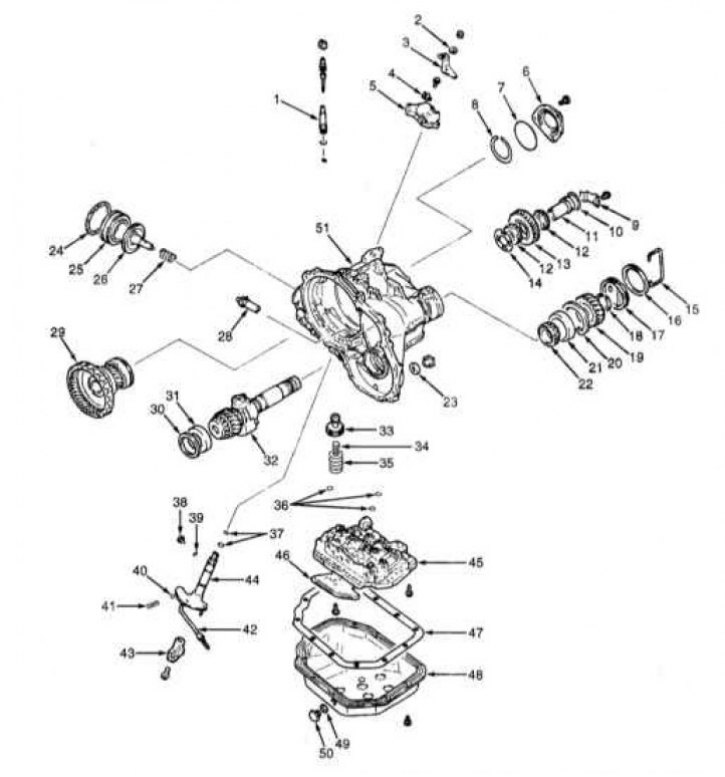
AT F3A21 design
1 - Control cable; 2 - Spring washer; 3 - Control lever; 4 - Retainer; 5 - PNP sensor switch; 6 - Bearing holder; 7 - Sealing ring; 8 - Retaining ring; 9 - Stop bar; 10 - Sealing ring; 11 - Intermediate gear shaft; 12 - Inner bearing race; 13 - Intermediate gear; 14 - Distance ring; 15 - Retainer; 16 - Retaining ring; 17 - Transfer shaft cover; 18 - Retaining ring; 19 - Driven gear; 20 - Retaining ring; 21 - Outer race; 22 - Inner bearing race; 23 - Sealing gasket; 24 - Retaining ring; 25 - Kickdown Servo Clutch; 26 - Kickdown servo piston; 27 - Spring; 28 - Anchor rod; 29 - Output flange; 30 - Distance ring; 31 - Outer race; 32 - Transfer shaft with control regulator; 33 - Hydraulic accumulator piston; 34 - Inner spring; 35 - Outer spring; 36 - Sealing ring; 37 - Sealing ring; 38 - Set screw; 39 - Sealing ring; 40 - Locking ball; 41 - Spring; 42 - AT parking position spacer rod; 43 - Thrust rod stop; 44 - Control rod; 45 - Valve assembly; 46 - Oil filter; 47 - Sealing gasket; 48 - Oil pan; 49 - sealing gasket; 50 - Drain plug; 51 - Transmission housing
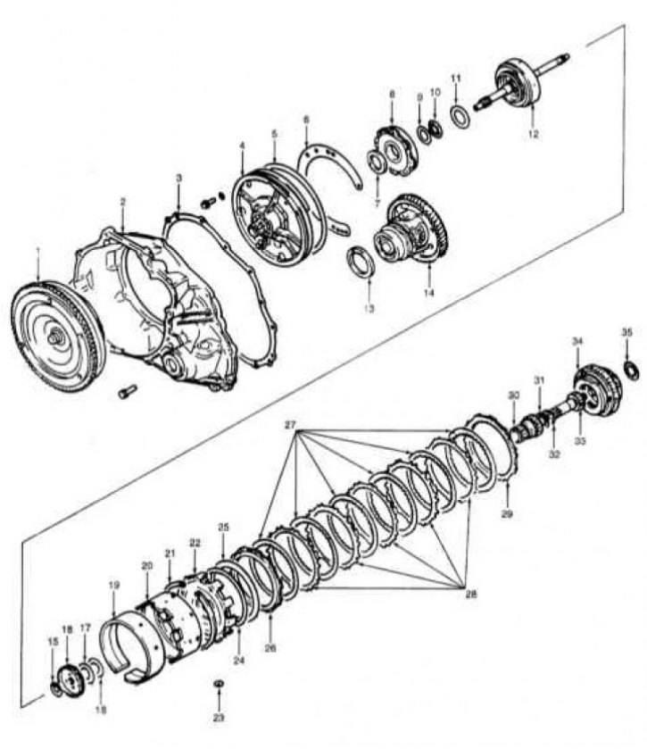
F3A21 Transmission Internal Component Design
1 - Rotation converter; 2 - Converter dome; 3 - Sealing gasket; 4 - Oil pump; 5 - Sealing ring; 6 - Sealing gasket; 7 - Thrust washer No.1; 8 - Assembling the front clutch; 9 - Thrust collar No.3; 10 - Thrust bearing No.4; 11 - Thrust washer No.2; 12 - Assembling the rear clutch; 13 - Distance ring; 14 - Differential; 15 - Thrust bearing No.6; 16 - Clutch hub; 17 - Thrust collar No.7; 18 - Thrust bearing No.8; 19 - Kickdown mode activation brake band; 20 - Brake drum kickdown mode activation; 21 - Retaining ring; 22 - Central stop; 23 - Sealing ring; 24 - Wave Washer; 25 - Return spring; 26 - Pressure plate; 27 - Brake discs; 28 - Brake plates; 29 - Reactive plate; 30 - Reverse sun gear; 31 - Thrust bearing No.9; 32 - Thrust collar No.10; 33 - Forward gear sun gear; 34 - Planetary gear holder; 35 - Thrust bearing No.12
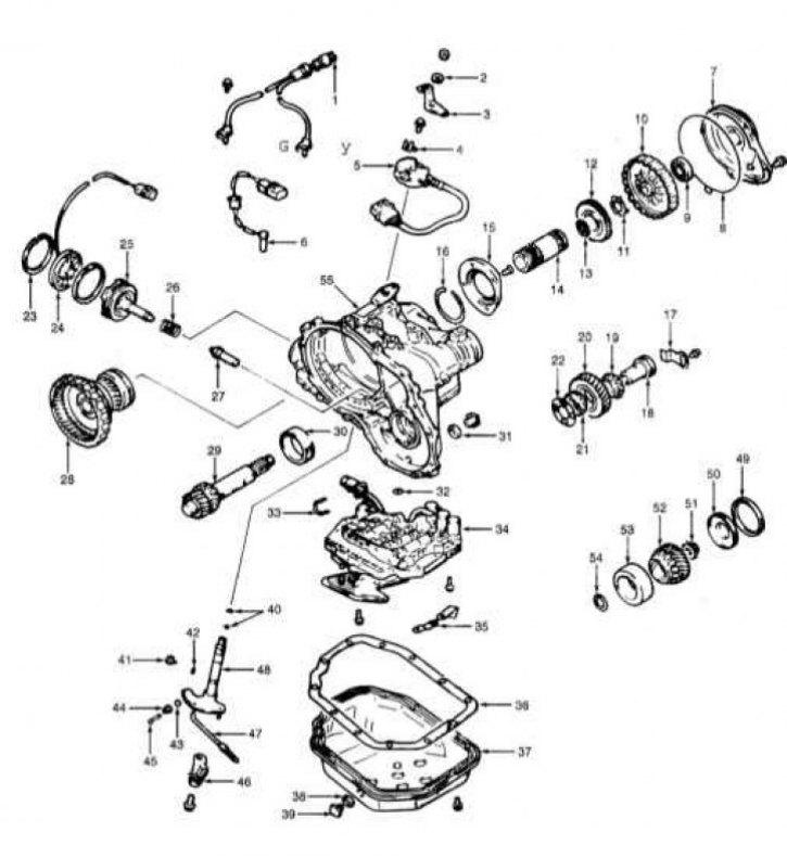
F4A20 Series Transmission Design
1 - Pulse generator; 2 - Spring washer; 3 - Control lever; 4 - Retainer; 5 - PNP sensor switch; 6 - ATF temperature sensor; 7 - Clutch end cover; 8 - Sealing ring; 9 - Bearing; 10 - Clutch end sleeve; 11 - Thrust washer; 12 - Clutch end sleeve hub; 13 - Thrust bearing No.13; 14 - Clutch end sleeve axle; 15 - Bearing holder; 16 - Retaining ring; 17 - Stop bar; 18 - Intermediate gear shaft; 19 - Inner bearing race; 20 - Intermediate gear; 21 - Inner bearing race; 22 - Distance ring; 23 - retaining ring; 24 - Servo kickdown switch sensor; 25 - Kickdown servo piston; 26 - Spring; 27 - Anchor rod; 28 - Output flange; 29 - Transfer shaft; 30 - Outer race; 31 - Sealing gasket; 32 - Sealing ring; 33 - Retainer; 34 - Valve assembly; 35 - Retainer; 36 - Sealing gasket; 37 - Oil pan; 38 - Sealing gasket; 39 - Drain plug; 40 - Sealing ring; 41 - Set screw; 42 - Sealing ring; 43 - Locking ball; 44 - Retainer saddle; 45 - Lock spring; 46 - Thrust rod stop; 47 - Transmission parking position spacer rod; 48 - Control rod; 49 - Sealing ring; 50 - Transfer shaft cover; 51 - Lock nut; 52 - Driven gear; 53 - Outer race; 54 - Distance ring; 55 - Transmission housing
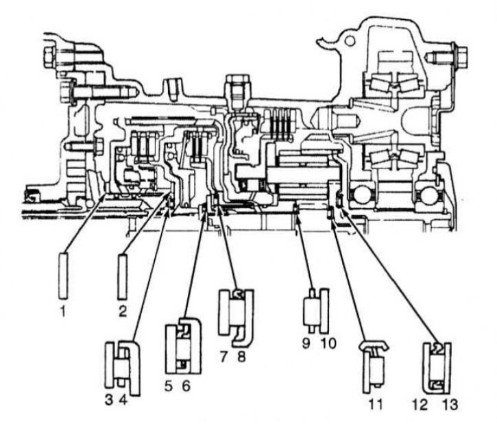
Layout of thrust bearings, races and washers on the F3A21 transmission
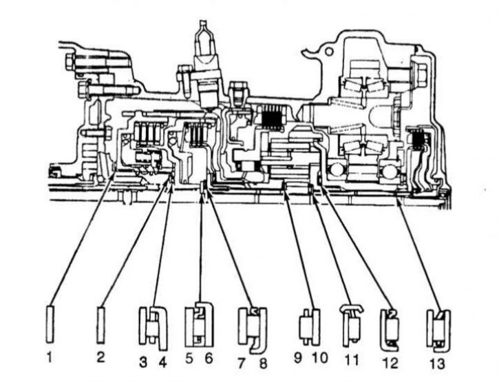
Layout of thrust bearings, races and washers on F4A20 series transmissions
Major repairs of ATs require a large number of precision measurements, require the performer to be able to use special tools and, in view of the above, its implementation is beyond the skill level of the average amateur mechanic.
For confident car enthusiasts, this Section provides a quick description of the procedures for disassembling and assembling the AT, as well as illustrative material on the design of individual, most typical transmission components.
Disassembling AT
Transmission F3A21
Note: This assumes the transmission has already been removed from the vehicle and placed on a mounting stand/workbench.
1. The design of the AT F3A21 is shown in the illustrations.
2. Before disassembling the transmission, plug all openings in the crankcase and thoroughly wipe the outer surface of the latter. Remove the rotation converter and turn the transmission over with the pan down.
3. Measure the axial play of the primary shaft, remove the distributor shaft cover and measure the axial play of the latter. Record the measurement results.
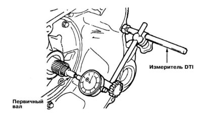
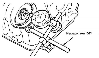
4. Remove the start enable switch sensor (see Section Removal, installation and adjusting the start enable switch sensor).
5. Remove the oil pan with the sealing gasket and filter.
6. Remove the ATF temperature sensor, push the solenoid valve wiring harness grommet and the solenoid valve connector into the transmission case.
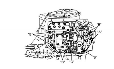
7. Disconnect the throttle cable, then remove the mounting bolts and valve assembly.
Attention! Try not to let the manual valve fall out of the assembly! Do not forget to remove the sealing ring installed between the assembly housing and the transmission housing - the ring must be replaced without fail. Remove the piston and accumulator springs.
8. Remove the rotation converter dome, oil pump assembly and thrust washer. Remove the differential assembly with the spacer ring. Remove the primary shaft of the AT complete with the front and rear clutches.
9. Remove the thrust bearing bushing and clutch hubs. Remove the thrust washer and bearing. Remove the kickdown drum and band. Remove the snap ring, piston, spring and anchor rod of the kickdown servo.
10. Remove the planetary gear assembly.
11. Remove the wave and return springs, pressure, brake and reaction discs and plates.
Note: Try to remember the installation position of the return spring.
12. Unscrew the bolt and remove the locking plate of the transfer case intermediate gear axle. Using a special key (MD998334) remove the intermediate gear. Remove the two inner bearing races and the gear spacer ring.
13. Remove the output flange bearing retainer with the sealing ring. Remove the retaining ring from the outer bearing race. Remove the internal gear assembly with the output flange, transfer case pinion and bearing.
14. Remove the retaining ring from the rear transfer shaft journal. Using a brass drift against the rear end of the shaft, tap the latter flush with the surface mating with the engine - the driven gear of the transfer mechanism should come off.
15. Remove the retaining ring, then (if necessary) remove the inner and outer races of the tapered roller bearing. Remove the spacer rod stop and the manual control shaft, remove the steel ball and spring.
Transmissions series F4A20 (F4A22/23/33/51)
Note: This assumes the transmission has already been removed from the vehicle and placed on a mounting stand/workbench.
1. The design of the AT series F4A20/30/50 is shown in the illustrations.
2. Before disassembling the transmission, plug all openings in the crankcase and thoroughly wipe the outer surface of the latter. Remove the rotation converter and turn the transmission over with the pan down.
3. Measure the value of the primary shaft axial clearance. Record the measurement result.
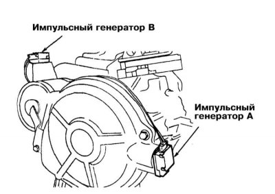
4. Remove pulse generators A and B and the PNP switch sensor.
5. Remove the kickdown servo switch sensor.
6. Remove the oil pan with the sealing gasket and filter. Remove the ATF temperature sensor.
7. Disconnect the electrical wiring from the solenoid valve and remove the valve assembly.
8. Remove the end cover and the clutch located underneath.
9. Remove the end coupling hub, thrust bearing and coupling shaft.
10. Remove the torque converter dome, oil pump assembly and thrust washer.
11. Remove the differential assembly with the spacer ring.
12. Remove the primary shaft assembly with the front and rear clutches.
13. Remove the thrust bearing and clutch hub. Remove the thrust collar and bearing.
14. Remove the kickdown brake band and drum.
15. Remove the kickdown servo retainer, piston and spring. Remove the anchor rod. Remove the snap ring and centre stop. Remove the forward and reverse sun gears. Remove the planetary assembly retainer with bearing. Remove the thrust race and bearing. Remove the wave washer, return spring, pressure plate, brake discs/plates and reaction plate - try to remember the installation position of the return spring.
16. Remove the end bearing holder - use a drift if necessary.
17. Unscrew the bolt and remove the locking plate of the transfer case intermediate gear axle. Using a special key (MD998334) remove the intermediate gear. Remove the intermediate gear shaft and remove the two inner bearing races and the gear spacer ring.
18. Remove the end bearing retaining ring. Remove the internal gear assembly with the output flange, transfer case drive gear and bearing from the crankcase. Remove the transfer case cover.
19. Loosen the lock nut of the transfer shaft (the nut has a left-hand thread). Using a press, press out the shaft. Using a puller, remove the transfer shaft bearing. Unscrew the set screw and remove the manual control rod with the stop of the spacer rod.
Maintenance of individual components
1. As mentioned above, due to the complexity of the procedures for servicing the components of the automatic transmission during its major repairs, the latter should be performed by specialists from the Mitsubishi branded auto service station.
2. This Section provides illustrative material that allows the reader with a technical education to form a general idea of the design and assembly and maintenance procedures for individual units and components of the automatic transmission. In addition, some adjustment parameters and dimensional characteristics are provided.
ATF oil pump
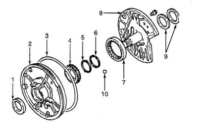
Oil pump design
1 - Seal; 2 - Body; 3 - Sealing ring; 4 - Drive gear; 5 - Seal; 6 - Retaining ring; 7 - Driven gear; 8 - Reaction shaft support; 9 - Sealing rings; 10 - Control ball
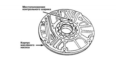
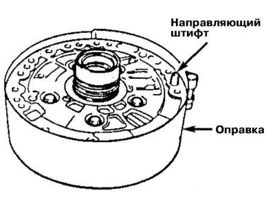
Make sure that the mounting bolts are tightened to the required torque during assembly; finally, check the free rotation of the pump gears.
 |  |
Front clutch
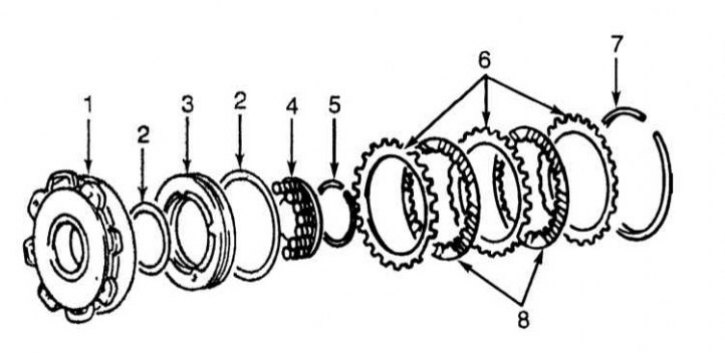
Front clutch design AT
1 - Front clutch holder; 2 - Sealing rings; 3 - Front clutch piston; 4 - Return spring; 5 - Retaining ring; 6 - Clutch reaction plates; 7 - Retaining ring (selected); 8 - Clutch discs
When assembling, make sure that the gap between the retaining ring and the reaction plate of the assembly meets the requirements Specifications, - retaining rings of various thicknesses are produced in the range of 1.6÷3.0 mm with a step of 0.10 mm. do not forget to replace the sealing rings.
Rear clutch
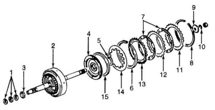
Rear clutch design AT
1 - Sealing rings (3); 2 - Rear clutch holder; 3 - Seal; 4 - Rear clutch piston; 5 - Sealing ring; 6 - Wave washer; 7 - Clutch discs; 8 - Retaining ring; 9 - Thrust collar; 10 - Retaining ring; 11 - Reactive plate; 12 - Clutch plate; 13 - Pressure plate; 14 - Return spring; 15 - Sealing ring
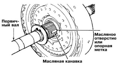
The clearance of the retaining ring is adjusted by selecting a ring of the appropriate thickness. Make sure that the oil groove of the primary shaft is aligned with the reference mark of the clutch holder. Do not forget to replace the sealing rings.
End clutch (F4A20 series transmissions only)
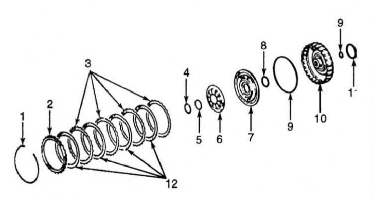
Clutch face design (F4A20 series transmissions only)
1 - Retaining ring; 2 - Reactive plate; 3 - Clutch plates; 4 - Retaining ring; 5 - Washer; 6 - Return spring; 7 - Clutch piston; 8 - Sealing ring; 9 - Seal; 10 - End coupling holder; 11 - Sealing ring; 12 - Clutch discs
In this coupling, the retaining ring is selected from a thickness range of 1.05÷2.05 (step = 0.25 mm). Do not forget to replace the sealing rings.
Low gear and reverse brake assembly
Don't forget to replace the sealing ring.
Planetary assembly
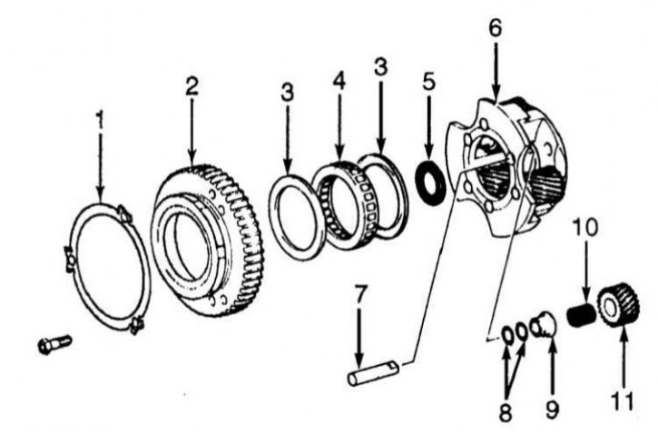
Design of the planetary assembly AT
1 - Locking plate; 2 - Outer race of one-way clutch; 3 - End plate; 4 - One-way clutch; 5 - Thrust bearing; 6 - Planetary assembly holder; 7 - Axis of satellites; 8 - Front thrust washers; 9 - Spacer sleeve; 10 - Roller; 11 - Satellite
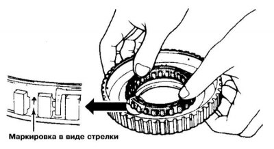
Make sure the one-way coupling is seated correctly in the outer race. Tighten all fasteners to the required torque.
Internal gear and transfer assembly
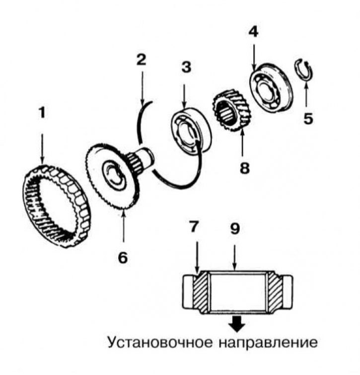
Internal gear and transfer assembly
1 - Internal gear; 2 - Retaining ring; 3 - Bearing; 4 - Bearing; 5 - Retaining ring; 6 - Output flange; 7 - Groove; 8 - Transfer case drive gear; 9 - Transfer case drive gear; 10 - Installation direction
The nominal thickness of the outlet flange retaining ring is 0÷0.06 mm.
Transfer shaft and control valve assembly (F3A21 transmission)
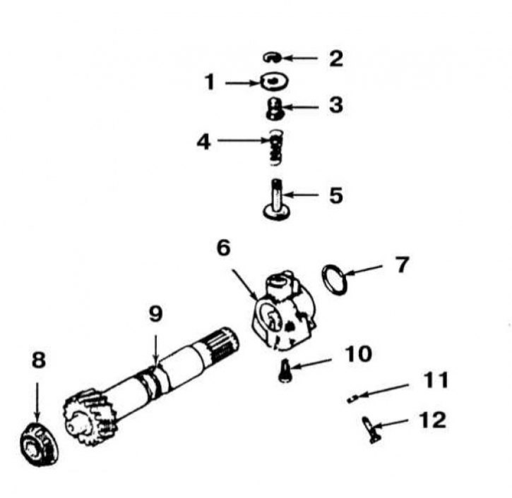
Assembly of the transfer shaft and the transmission control regulator F3A21
1 - Regulator weight; 2 - Retaining ring; 3 - Regulator valve; 4 - Spring; 5 - Spring plate; 6 - Regulator; 7 - Sealing ring (3); 8 - Bearing; 9 - Transfer shaft; 10 - Filter; 11 - Lock nut; 12 - Set screw
Make sure that the required tightening forces are observed for the fasteners.
Differential
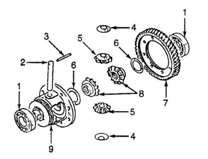
AT differential design
1 - Bearing; 2 - Axle of satellites; 3 - Locking pin; 4 - Washer; 5 - Satellites; 6 - Distance rings; 7 - Driven gear of the main transmission; 8 - Differential side gears; 9 - Differential box
1. When replacing side gears, use spacer rings of medium thickness (0.93÷1.00 mm).
2. The gear engagement play should be the same in both directions and not exceed the range of 0.03÷0.15 mm - adjustment is made by selecting spacer rings. Rings of the following thickness are produced: 0.75÷0.82 mm; 0.83÷0.92 mm; 0.93÷1.00 mm; 1.01÷1.08 mm and 1.09÷1.16 mm.
Kickdown servo piston
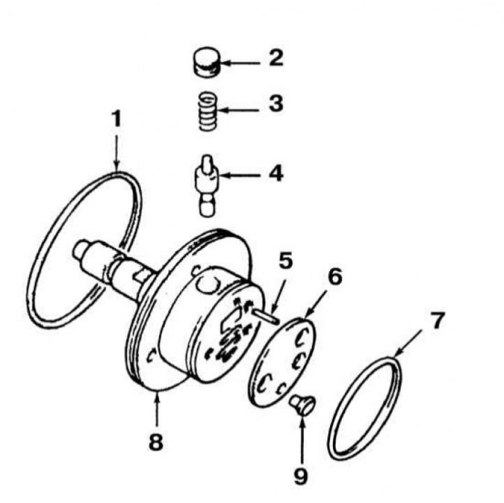
Kickdown servo piston design
1 - Sealing ring; 2 - Cork; 3 - Spring; 4 - Valve; 5 - Pin; 6 - Lid; 7 - Sealing ring; 8 - Servo piston; 9 - Screw
Wet components with transmission fluid before assembly.
Speedometer drive gear
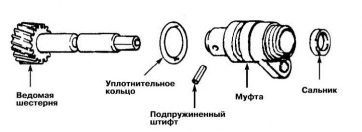
The spring pin, seal and O-ring must be replaced without fail. Lightly lubricate the driven gear with engine oil before installation.
Valve assembly
Note: Never clamp the valve body in a vice - the slightest deformation can cause the valves to jam and leak! Before installation, thoroughly rinse all components in clean ATF and do not wipe them with a rag.
AT F3A21
Disassembly
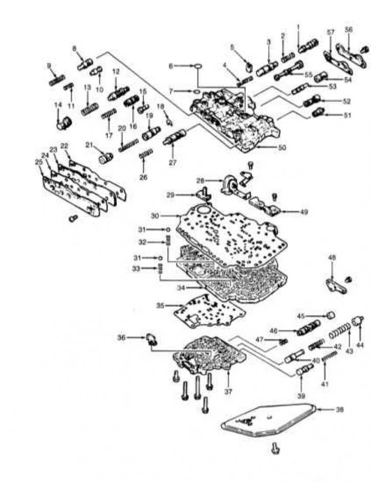
Valve assembly design AT F3A21
1 - Kickdown valve; 2 - Kickdown valve spring; 3 - Throttle valve; 4 - Throttle valve spring; 5 - Thrust retainer; 6 - Sealing ring; 7 - Sealing ring; 8 - Range control valve; 9 - Range control valve spring; 10 - Rotary converter control valve; 11 - Rotary converter control valve spring; 12 - Regulator valve; 13 - Regulator valve spring; 14 - Adjusting screw; 15 - Filter; 16 - 1/2 gear shift valve; 17 - 1/2 gear shift valve spring; 18 - Retaining ring; 19 - 2/3 gear control valve; 20 - Spring control valve 2/3 gears; 21 - Engine braking mode valve; 22 - Sealing gasket; 23 - Front end plate; 24 - Sealing gasket; 25 - Front end cover; 26 - 2/3 gear shift valve spring; 27 - 2/3 gear shift valve; 28 - Assembling the throttle cam; 29 - Spring guide; 30 - Upper separator plate; 31 - Steel Ball; 32 - Line pressure relief spring; 33 - Low pressure release spring; 34 - Intermediate plate; 35 - Lower separator plate; 36 - Locking pin; 37 - Lower section of valve assembly; 38 - Filter; 39 - Pressure reducing valve; 40 - Accumulator valve; 41 - Pressure reducing valve spring; 42 - Accumulator valve spring; 43 - Accumulator valve spring; 44 - Accumulator valve plug; 45 - Bushing; 46 - Clutch control valve; 47 - Control valve spring; 48 - End cap; 49 - Reinforcement plate; 50 - Upper section of valve assembly; 51 - 2/3 gear shift valve plug; 52 - 1/2 gear shift valve plug; 53 - Regulator plug; 54 - Regulator plug; 55 - Manual valve; 56 - Rear end cover; 57 - Sealing gasket
1. The design of the valve assembly of the F3A21 transmission is shown in the illustration.
2. Remove the throttle cam assembly. Remove the 13 mounting bolts and remove the lower valve assembly section with the lower divider plate.
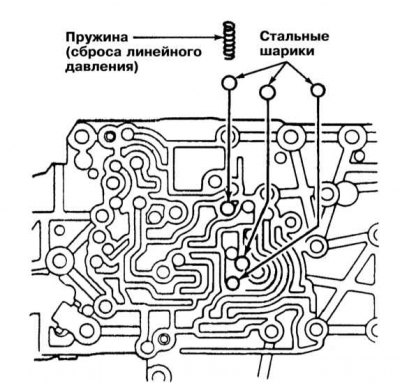
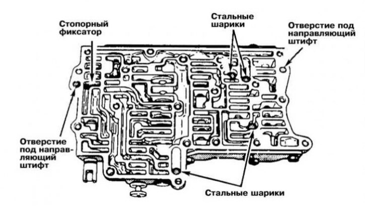
3. Remove the line pressure relief spring and 3 steel balls. Separate the lower valve assembly and intermediate plate. Remove the 4 steel balls from the upper assembly. Remove the solenoid valve, reinforcement plate and upper separator plate. Remove the steel ball and spring from the intermediate plate.
Checking the condition of components and assembly
1. Thoroughly rinse all assembly components in ATF and do not wipe them with a rag. Check the condition of the working surfaces of the valves and the assembly body.
2. Assess the condition of the valve springs. Measure the height of the springs and compare the measurement result with the requirements of the Specifications. Replace if necessary.
3. Lubricate with transmission fluid and install all valves and valve springs in their regular places. Screw in and tighten the plugs.
4. Make sure all mounting bolts are tightened to the required torque. When joining the upper and lower sections of the assembly, do not forget to install steel balls and guide pins.
AT series F4A20
Disassembly
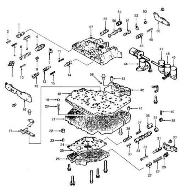
Valve assembly design AT series F4A20
1 - Pressure control valve; 2 - Pressure control valve spring; 3 - Rotary converter control valve; 4 - Converter control valve spring; 5 - Regulator valve; 6 - Regulator valve spring; 7 - Adjusting screw; 8 - Locking pin; 9 - Shift control valve plug; 10 - Spring; 11 - Rear clutch release valve spring; 12 - Bleed valve B rear clutch; 13 - Rear clutch release valve A; 14 - 2/3 and 3/4 gear shift valve; 15 - 2/3 and 3/4 gear shift valve spring; 16 - Front end cover; 17 - Valve stop; 18 - Upper separator plate; 19 - Steel Ball; 20 - Pressure release spring; 21 - Intermediate plate; 22 - Nut; 23 - Jet; 24 - Oil filter; 25 - Lower separator plate; 26 - Lower section of valve assembly; 27 - Pressure reducing valve; 28 - Pressure reducing valve spring; 29 - Adjusting screw; 30 - End cap; 31 - N/R Shift Control Valve; 32 - N/R shift valve spring; 33 - Spring, torque converter clutch control valve (TCC); 34 - TCC Control Valve; 35 - TCC control valve bushing; 36 - Clutch end valve; 37 - End clutch valve spring; 38 - End coupling valve plug; 39 - Stop; 40 - Pin; 41 - Guide bushing; 42 - Block; 43 - Tube; 44 - Pressure Control Solenoid Valve (PCSV); 45 - Shift Control Solenoid Valve B (SCSV-B); 46 - Shift Control Solenoid Valve A (SCSV-A); 47 - TCC Solenoid Valve; 48 - 1/2 gear shift valve; 49 - 1/2 gear shift valve spring; 50 - Rear end cover; 51 - Shift control valve; 52 - Thrust retainer; 53 - Valve plug B for switching control; 54 - N/R shift control valve bushing; 55 - N/R switching control valve; 56 - Manual valve; 57 - Upper section of valve assembly; 58 - Teflon ball
1. The design of the valve assembly of the F4A20 series transmissions is shown in the illustration.
2. Remove the manual and solenoid valves. Remove the stop retainer with the clamp. Unscrew the 13 mounting bolts and remove the lower section of the valve assembly.
(The text of the article was obtained from the website: MitsubishiMan)
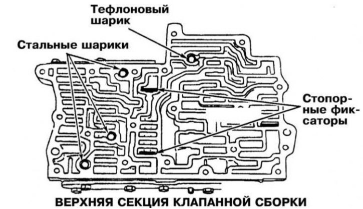
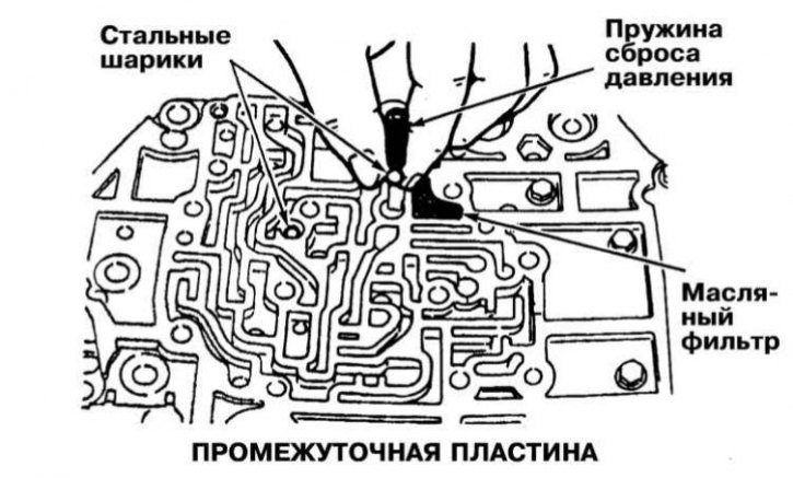
3. Remove the spacer plate from the intermediate plate. Remove the pressure release spring and remove the two steel balls and oil filter from the intermediate plate. Remove the 8 mounting bolts and remove the intermediate plate from the upper section of the valve assembly.
4. Remove three steel balls and one Teflon ball from the upper section of the valve assembly, also remove two locking clips. Unscrew the plugs and remove the springs and valves.
Checking the condition of components and assembly
1. Thoroughly rinse all assembly components in ATF and do not wipe them with a rag. Check the condition of the working surfaces of the valves and the assembly body.
2. Assess the condition of the valve springs. Measure the height of the springs and compare the measurement result with the requirements of the Specifications. Replace if necessary.
3. Lubricate with transmission fluid and install all valves and valve springs in their regular places. Screw in and tighten the plugs. Make sure that all mounting bolts are tightened to the required force.
Transmission assembly
Note: All components should be lubricated with ATF before installation, and O-rings and seals with petroleum jelly. Petroleum jelly can also be used to temporarily hold bearings, thrust washers and washers - ensure that the components are oriented correctly when installed on the assembly.
Transmission F3A21
1. Before installation, measure the clearance of the low/reverse brake assembly and, based on the measurement results, select a pressure plate of the appropriate thickness (see below).
2. Install the reaction and brake plates of the assembly. Install the pressure plate of the selected thickness. Install the return spring, - make sure that the spring is installed correctly.
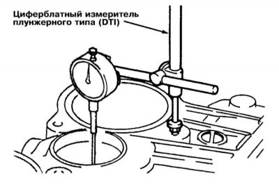
3. Lubricate and install the wave spring on the center stop with petroleum jelly. Place the center stop in the housing and install the retaining ring. Using a DTI dial gauge mounted to the rear of the transmission case, determine the low/reverse brake assembly clearance by inserting the feeler gauge into the transfer shaft mounting hole until the plunger is perpendicular to the brake assembly reaction plate.
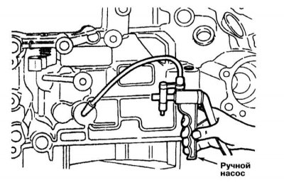
4. Using a hand pump, pump air into the low/reverse brake assembly and read the DTI meter reading. By selecting a pressure plate of the appropriate thickness, achieve the required clearance setting (0.80÷1.00 mm).
5. Transfer the transmission housing to a workbench and place it with the surface mating with the valve assembly facing up. Insert the output flange into the housing. Secure the flange with a retaining ring, installing the latter on the outside of the housing. Install the intermediate gear spacer ring of the transfer case into the housing.
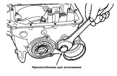
6. Install the transfer case intermediate gear assembly with the shaft. Using the special key MD998344, tighten the intermediate shaft.
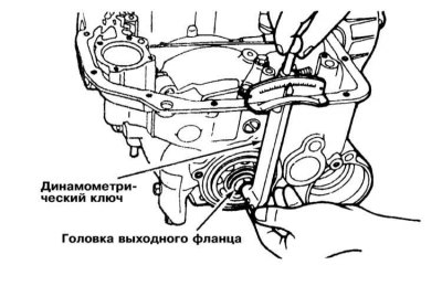
7. Insert the MD998343 head into the output flange and measure the flange turning torque using a torque wrench. The required value is 0.8 Nm - if necessary, make the appropriate adjustment by tightening/loosening the shaft tightening force.
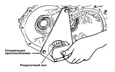
8. After completing the preload adjustment, install the intermediate shaft lock plate. Install the bearing retainer, insert the transfer shaft into the assembly and install the MD998319 tool onto it.
9. Using a special driver, seat the bearing on the transfer shaft, then press the outer race into the crankcase. Install the driven gear of the transfer shaft, then seat the retaining ring on the shaft journal.
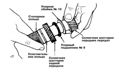
10. Place thrust collar No.13 on the flange. Insert the planetary assembly holder with thrust bearing No.12 into the transmission housing. Install both sun gears into the planetary assembly holder.
11. Install the low/reverse brake assembly complete with the previously installed pressure plate. Install the return spring. Lubricate with technical petroleum jelly and install the wave spring on the central stop.
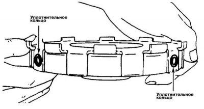
12. Insert two new sealing rings into the hydraulic holes of the central stop - lubricate the rings with transmission fluid before installing.
13. Install the center stop assembly, making sure that the sealing rings and wave spring do not fall out. Secure the assembly with the retaining ring.
14. Install the kickdown assembly band anchor rod. After replacing the O-rings, install the servo assembly. Place new O-rings on the inner and outer edges of the servo sleeve - note that the rings differ in cross-section shape (the inner edge has a round section ring, the outer edge has a D-shaped ring). Insert the sleeve into the transmission case and secure it with a retaining ring. Install the brake band, securing its edges to the anchor rod and the servo piston rod.
15. Install the drum and place the brake band on it. Lubricate the thrust bearing #8 with technical petroleum jelly and place it on the kickdown servo brake drum. Also having lubricated it with petroleum jelly, install the thrust collar #7 on the rear clutch hub.
16. Place the rear clutch hub on the splines of the planetary sun gear and install thrust bearing No.6 on the outside of it. Install thrust washer No.2 and thrust bearing No.4 on the rear side of the clutch. Connect the front clutch to the rear and seat the assembly in the transmission case. Install the differential.
17. If the axial play of the primary shaft measured during dismantling was outside the permissible range, correct it by selecting the thickness of thrust collar No.3 and thrust washer No.1. The required value of axial play is 0.30÷1.00 mm.
18. After replacing the sealing gasket, install the oil pump assembly in its regular place. Screw in the mounting bolts and tighten them to the required force. Finally, check the axial play of the primary shaft once again.
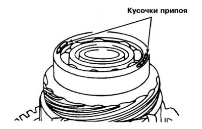
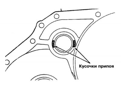
19. Place two pieces of tin solder 10 mm long and 3 mm in diameter on both sides of the outer race of the differential bearing. Place the same pieces of solder on the mating surface of the rotation converter dome in the area of the hole for installing the transfer shaft. Install the bearing race in the dome.
 |  |
20. Install the converter dome without the gasket and tighten its mounting bolts with a force of 19÷23 N·m.
21. Loosen the bolts, remove the dome and measure the thickness of the flattened solder pieces. Select the differential spacer ring according to the formula: solder thickness plus sealing gasket thickness (0.38 mm), minus differential axial clearance (0÷0.15 mm).
22. The thickness of the transfer shaft spacer ring is determined as follows: The thickness of the solder plus the thickness of the sealing gasket (0.38 mm), plus the value of the bearing preload (0.10÷0.15 mm).
23. Install the appropriate transfer shaft bearing preload adjustment spacer ring into the converter dome.
Note: Rings are available in thicknesses ranging from 0.82 mm to 1.69 mm in 0.03 mm increments. Install the transfer shaft bearing race. Install the appropriate spacer ring on the differential bearing - rings are selected from a thickness range of 1.31 - 2.13 mm.
24. Lubricate the serrated areas of the transmission housing mating surface with silicone grease, then install the sealing gasket. Install the converter dome. Screw in the mounting bolts and tighten them to the required torque.
25. Insert the manual control lever axle (without the sealing ring) into the crankcase until it stops. Place the sealing ring in the groove protruding from the outside of the crankcase. Pull the axle back slightly and screw in the set screw.
26. Install the spacer rod stop. Install three oil flow sealing rings on the valve assembly. Lubricate the accumulator piston seals with ATF and seat the piston in the transmission housing. Install the valve assembly in its regular place and tighten its mounting bolts to the required force.
27. Install the oil filter. Screw in the mounting bolts and tighten them to the required torque. After replacing the sealing gasket, install the oil pan with the magnets inserted into it. Tighten the pan mounting bolts to the required torque. Lubricate the mating surface of the converter with transmission fluid and install the cover on the dome. Measure the distance between the cover and the end of the gear: the installation depth should be approximately 12.0 mm.
F4A20 Series Transmissions
1. Before starting assembly, measure the clearance of the low/reverse brake assembly and select a pressure plate of the appropriate thickness.
2. Install the brake assembly reaction plate, brake plates and discs into the transmission housing - ensure that the pressure plate is installed correctly. Install the return spring correctly.
3. Lubricate the wave spring with technical petroleum jelly and install it on the center stop assembly. Install the center stop into the transmission housing and secure it with the circlip. Using the DTI gauge, check the clearance of the low/reverse brake assembly. The brake assembly is activated using a hand pump), - select a pressure plate of the appropriate thickness (the clearance should not exceed the range of 1.00÷1.20 mm).
4. Remove all previously installed components.
5. Install the outer race of the transfer shaft bearing into the transmission case. Place the bearings on the shaft, insert the assembly into the case and center it using the MD998319 tool.
6. Place a spacer ring of maximum thickness (1.80 mm) on the transfer shaft journal. Press the driven gear of the transfer shaft into its regular place. Clamp the shaft journal in a vice and tighten its lock nut with the required force (215 N·m).
7. Measure the axial clearance of the transfer shaft. The measurement result should not exceed the permissible range (0÷0.025 mm), - select a spacer ring of the appropriate thickness (rings are available in a thickness range of 1.82÷2.13 mm with a step of 0.06 mm). After adjusting the gap, calk the lock nut.
8. Lubricate the intermediate gear of the transfer case and press it against the AT housing. Install two tapered roller bearings, insert the intermediate gear assembly with bearings into the housing and thread the shaft into it from the outside.
9. Tighten the intermediate gear shaft with the MD998344 tool. Insert the MD998906 head into the output flange and measure the flange turning torque with a torque wrench. The required value is 0.8 N·m - if necessary, make the appropriate adjustment by tightening/loosening the shaft tightening force.
10. Once the preload adjustment is complete, install the intermediate shaft lock plate. Install the bearing retainer, install the new screws and tighten them to the specified torque.
11. Place the planetary assembly holder with thrust bearing No.12 into the transmission housing. Install thrust bearing No.9 and race No.10 onto the forward sun gear. Proceeding in a similar manner, assemble the reverse sun gear and install it into the holder.
12. Install the low-range/reverse brake assembly complete with the pressure plate selected and installed earlier. Install the return spring. Lubricate with technical petroleum jelly and install the wave spring on the central stop. Insert two new sealing rings into the hydraulic holes of the central stop - lubricate the rings with transmission fluid before installing.
13. Install the central stop assembly, making sure that the sealing rings and wave spring do not fall out. Secure the assembly with the retaining ring, making sure that the lock of the latter does not end up facing the mounting hole of the pulse generator A.
14. Install the kickdown brake band assembly anchor rod. Place new O-rings on the servo piston - note that the rings differ in diameter and cross-section shape. Place the new O-ring in the groove on the coupling. Insert the spring, piston and servo coupling into the transmission case and secure the assembly with a retaining ring. Install the brake band, securing its edges to the anchor rod and servo piston rod.
15. Install the drum and place the brake band on it. Lubricate the thrust bearing #8 with technical petroleum jelly and place it on the kickdown servo brake drum. Also having lubricated it with petroleum jelly, install the thrust collar #7 on the rear clutch hub.
16. Place the rear clutch hub on the splines of the planetary sun gear and install thrust bearing No.6 on the outside of it. Install thrust washer No.2 and thrust bearing No.4 on the rear side of the clutch. Connect the front clutch to the rear and seat the assembly in the transmission case. Install the differential.
17. If the axial play of the primary shaft measured during dismantling was outside the permissible range, correct it by selecting the thickness of thrust collar No.3 and thrust washer No.1. The required value of axial play is 0.30÷1.00 mm.
18. After replacing the sealing gasket, place the oil pump assembly in its regular place. Screw in the mounting bolts and tighten them to the required force. Finally, check the axial play of the primary shaft once again.
19. Place two pieces of tin solder 10 mm long and 3 mm in diameter on both sides of the outer race of the differential bearing. Without a gasket, install the converter dome and tighten its mounting bolts with a force of 19÷23 N·m.
20. Loosen the bolts, remove the dome and measure the thickness of the flattened solder pieces. Select the differential spacer ring according to the formula: solder thickness plus sealing gasket thickness (0.38 mm), minus differential axial clearance (0÷0.15 mm).
21. Install the appropriate spacer ring on the differential bearing - rings are selected from a thickness range of 1.85÷65.28 mm with a step of 0.09 mm.
22. Lubricate the serrated areas of the mating surface of the transmission housing with silicone grease, then install the sealing gasket. Press the converter dome to the transmission. Screw in the mounting bolts and tighten them to the required torque.
23. Install the shaft of the end clutch (with the long, splined journal facing the converter) onto the end of the clutch return spring and fit the thrust washer.
24. Check the proper functioning of the clutch couplings by supplying air to the corresponding fittings.
Attention! Only absolutely dry air may be pumped into the transmission! Do not raise the pressure in the transmission higher than 1.75 kgf/cm².
25. Insert the manual control lever axle (without the sealing ring) into the crankcase until it stops. Place the sealing ring in the groove protruding from the outside of the crankcase. Pull the axle back slightly and screw in the set screw. Install the ball and the retainer spring.
26. Install the spacer rod stop. Lubricate the accumulator piston seals with ATF and seat the piston in the transmission housing. Install the brake assembly oil flow sealing ring on top in the central part of the valve assembly and seat the latter in its regular place. Screw in and tighten the mounting bolts to the required force.
27. Install the oil filter. Screw in the mounting bolts and tighten them to the required torque. After replacing the sealing gasket, install the oil pan with the magnets inserted into it. Tighten the pan mounting bolts to the required torque. After replacing the sealing ring, install the kickdown servo switch in its regular place and secure it with a retaining ring. Install the PNP switch and the manual control lever.
28. Adjust the PNP switch. Install pulse generators A and B. Lubricate the converter mating surface with transmission fluid and install the cover on the dome. Measure the distance between the cover and the end of the gear: the installation depth should be approximately 12.0 mm.