



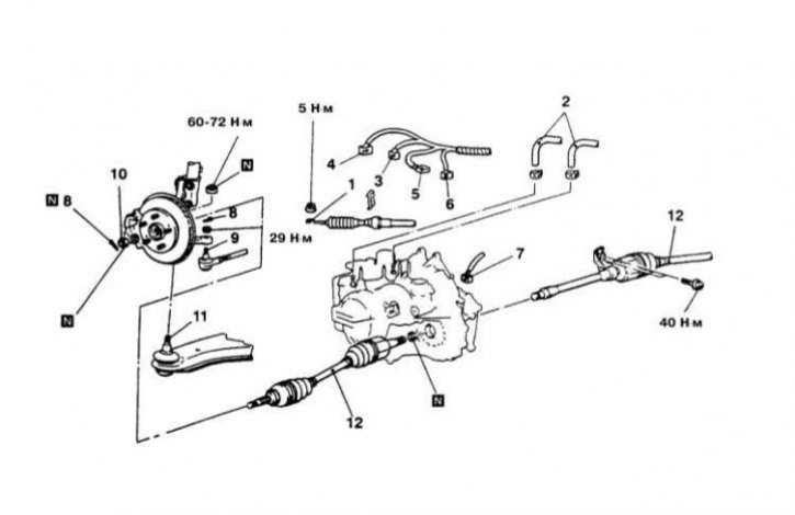
AT F4A51 installation details on Diamante models, left rear view (1 of 2)
1 - Connection point for the AT shift control cable; 2 - Oil cooler hoses; 3 - Start Permission Switch (PNP) Sensor Wiring Connector; 4 - Electrical connector for the AT control solenoid valve; 5 - Input shaft speed sensor wiring connector; 6 - Secondary shaft speed sensor wiring connector; 7 - VSS Wiring Connector; 8 - Cotter pin; 9 - Tie rod end; 10 - Hub nut (drive shaft mounting nut); 11 - Ball joint of the lower suspension arm; 12 - Drive shaft assemblies
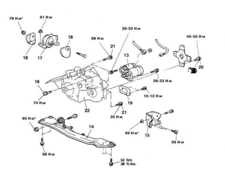
AT F4A51 installation details on Diamante models, left rear view (2 of 2)
13 - Starter; 14 - Central beam; 15 - Bracket of rear jet stop of power unit suspension; 16 - Upper transmission section fixing bolt; 17 - Powertrain suspension support bracket; 18 - Support limiter; 19 - Transmission dome cover; 20 - Drive disc mounting bolt; 21 - Lower transmission section fixing bolt; 22 - Transmission assembly
Diamante Models
Note: The final tightening of the fasteners marked with an asterisk is performed after the power unit has been lowered.
Removal
1. The installation details of the AT assembly on Diamante models are shown in the illustrations.
2. Disable the SRS (airbags) (see Chapter On-board electrical equipment).
3. Jack up the car and place it on supports.
4. Remove the front wheels.
5. Remove the side cover and engine crankcase protection.
6. Drain the ATF from the transmission case.
7. If the vehicle is equipped with the appropriate equipment, remove the front catalytic converter assembly.
8. Remove the exhaust pipe, main muffler and catalytic converter assembly.
9. Remove the steering tie rod end and the ball joint of the suspension arm from the steering knuckle assembly.
10. Unbolt the left drive shaft support bearing.
11. Using a pry bar, release the drive shafts from the transmission.
12. Remove the air cleaner assembly with the air intake hose attached to it.
13. Disconnect the engine wiring harness connector.
14. On models with active suspension (Active-ECS) remove the compressor assembly from the transmission and tie it up with wire - do not allow the compressor to hang from the air hose.
15. If equipped, remove the powertrain suspension reactive strut support bracket.
16. Disconnect the speedometer drive cable from the transmission.
17. Loosen the retaining clamp and disconnect the gear shift cable from the transmission.
18. Disconnect the oil cooler hoses from the transmission housing - immediately seal the open ends of the hoses to prevent dirt from entering the system.
19. Disconnect the wiring harness from the start enable switch, kickdown servo switch, pulse generator, ATF temperature sensor, and transmission shift control solenoid valve.
20. Support the transmission with a jack and remove the transmission support bracket.
21. Remove the three upper transmission-to-engine mounting bolts.
22. On 4WS models, remove the 4WS oil pump heat shield and remove the pump assembly - be careful not to put any strain on the oil hoses.
23. On models equipped with Active-ECS, disconnect the ride height sensor rod from the lower control arm assembly.
24. Remove the oxygen sensor mounting bolt from the right beam.
25. Remove the starter assembly.
26. Remove the support brackets blocking access to the rear cover of the transmission dome.
27. Remove the transmission dome/pan covers.
28. Remove the bolts securing the flexible disk to the rotation converter.
29. Remove the lower mounting bolts, separate the transmission from the engine and remove it from under the vehicle.
Installation
1. Press the transmission against the engine, screw in the mounting bolts and tighten them to the required torque (75 N·m)
2. Screw in the bolts securing the rotation converter to the drive disk and tighten them to the required torque (46÷53 N·m).
3. Install the transmission dome/sump covers.
4. Reinstall all powertrain mount brackets that were removed to gain access to the transmission rear cover.
5. Reinstall the starter.
6. Screw in the oxygen sensor wiring harness mounting bolt to the right beam and tighten it to the required torque (10÷12 N·m).
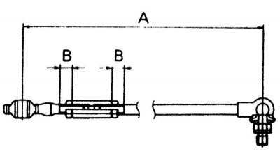
7. On models with Active-ECS, connect the suspension height sensor rod to the lower control arm. Adjust the length of the rod A, - the required value is 269÷270 mm.
8. If equipped, reinstall the 4WS pump and its heat shield. Tighten the pump and shield mounting bolts to the required torque (24 Nm).
9. Install the three upper transmission-to-engine mounting bolts. Tighten the bolts to the specified torque (75 N·m).
One of the top bolts is also used to secure the ground busbar.
10. Install the transmission suspension support bracket. Tighten the support fasteners (bolts and nuts) to the required torque (70 N·m).
11. Connect the electrical wiring to the AT switching control solenoid valve, the kickdown mode servo switch sensor, the pulse generator, the ATF temperature sensor, and the start-up enable sensor (PNP).
12. Connect the oil cooler hoses to the transmission and secure them to their fittings with new clamps.
13. Connect the shift cable to the transmission and secure it with a clamp.
14. Connect the speedometer drive cable to the transmission.
15. If equipped, install the powertrain suspension reactive strut bracket and tighten the nut of its through bolt to 50÷60 N·m. Tighten the two remaining bolts to 22 N·m.
16. On Active-ECS models, reinstall the air compressor assembly and tighten its mounting bolts to the specified torque (5 Nm).
17. Connect the engine wiring harness connector.
18. Install the air cleaner assembly with the air intake hose.
19. After replacing the retaining rings, seat the drive shafts in the transmission. Screw in the left shaft support bearing mounting bolt and tighten it to the required torque (45 N·m).
20. Install the steering tie rod end and the ball joint of the lower suspension arm into the steering knuckle assembly. Tighten the castle nuts of the ball pins to the required torque (60÷72 N·m: support and 30 N·m: tip). Lock the nuts with new cotter pins.
21. After replacing the sealing gaskets, reinstall the removed sections of the exhaust system.
22. Install the crankcase guard. Fill the transmission with the appropriate amount of ATF of the required grade (see Chapter Settings and ongoing maintenance).
23. Start the engine and check it for signs of developing leaks.
Galant models up to 1993.
Removal
1. On models equipped with a speed control system, remove the cruise control actuator assembly from its support bracket.
2. If equipped, disconnect the Active-ECS air compressor.
3. Drain the ATF from the transmission.
4. Remove the air cleaner assembly, integrated cooler and air duct sleeve.
5. After marking, disconnect the wiring from the solenoid valve, PNP switch, kickdown servo pulse generator and ATF temperature sensor.
6. Disconnect the speedometer drive cable and oil cooler lines from the transmission.
7. After disconnecting the electrical wiring, remove the starter assembly.
8. Remove the upper transmission-to-engine mounting bolts.
9. Support the transmission with a jack and remove the transmission suspension support bracket.
10. Jack up the car and place it on supports. Remove the crankcase protection elements.
11. Disconnect the steering rods and lower suspension arms from the steering knuckle assemblies.
12. Release the drive shafts from the transmission housing (to avoid damaging the inner CV joints, do not pull the shafts, but pry them up with a crowbar - try not to damage the seals). Tie the shafts to the underbody elements with wire.
13. On AWD models, disconnect the exhaust system and remove the transfer case.
14. Remove the lower cover of the transmission dome and unscrew the special bolts securing the flexible disk to the rotation converter. In order to provide alternate access to each of the bolts, turn the engine crankshaft by the pulley bolt using a socket wrench. Having unscrewed all the bolts, press the converter inside the transmission - if the converter remains on the engine, this will lead to oil getting into its hub, which is fraught with failure of the assembly.
15. Remove the lower mounting bolts, disconnect the transmission from the engine and remove it from under the vehicle.
Installation
1. Having fixed the rotation converter in the transmission, press the latter assembly to the engine. Screw in the drive disk mounting bolts and tighten them with the required force (46÷53 N·m). Screw in and tighten with a force of 48 N·m the transmission mounting bolts. Install the dome cover.
2. On all-wheel drive (AWD) models, install the transfer case assembly to the frame members. After replacing the sealing gaskets, install the removed exhaust system sections.
3. After replacing the retaining rings, insert the inner journals of the drive shafts into the transmission.
4. Insert the steering rod ends and suspension arm ball joints into the steering knuckles.
5. Install the transmission mount bracket.
6. Install the crankcase guard.
7. Install the starter.
8. Connect the speedometer drive cable and oil cooler hoses to the transmission.
9. Connect the wiring to the solenoid valve, PNP switch, kickdown servo pulse generator and ATF temperature sensor.
10. If equipped, reinstall the Active-ECS air compressor.
11. On models equipped with a speed control system, reinstall the cruise control actuator with its support bracket.
12. Fill the transmission with the correct amount of ATF of the required grade (see Chapter Settings and ongoing maintenance). On AWD models, check the transfer case fluid level.
13. Start the engine and let it idle for at least 2 minutes. Set the parking brake and move the selector lever successively to each of the provided positions, finally returning it to the "N" position.
14. Check the ATF level and make adjustments if necessary.
Galant models since 1994.
Removal
1. Disconnect the negative cable from the battery.
Warning! If the car stereo system is equipped with a security code, make sure you have the correct combination to activate the audio system before disconnecting the battery!
2. Remove the air cleaner assembly with the air intake hoses.
3. Drain the ATF from the transmission.
4. Loosen the nut securing the shift lever to the transmission. Loosen the clamp and disconnect the drive cable from the transmission.
5. Remove the shift cable support bracket.
6. After marking, disconnect the wiring from the speedometer, solenoid valve, PNP switch, pulse generator, kickdown servo and ATF temperature sensor.
7. Label and disconnect the oil cooler lines from the transmission.
8. Remove the mounting bolt and remove the feeler gauge with the guide tube from the transmission.
9. Remove and move aside the starter assembly.
10. Support the engine with a device such as MZ203827.
11. Remove the rear torque strut bracket of the powertrain suspension.
12. Remove the transmission mount bracket.
13. Remove the upper transmission mounting bolts.
14. Jack up the car and place it on supports.
15. Remove the front wheels.
16. Remove the right section of the crankcase guard.
17. Remove the cotter pin and disconnect the steering tie rod end from the steering knuckle assembly.
18. Disconnect the anti-roll bar strut from the damper fork assembly.
19. Disconnect the damper fork from the suspension control arm.
20. Release the ball joints of the lower and clamping arms and suspension from the steering knuckle.
21. Using a crowbar, release the drive shafts from the transmission and tie them with wire to the underbody elements of the car.
22. Remove the cover from the transmission dome.
23. Remove the through bolt of the front torque strut of the powertrain suspension.
24. Remove the beam and the right triangular bracket.
25. Unscrew the bolts securing the flexible disk to the rotation converter and press the latter into the transmission.
26. Support the transmission with a trolley jack and remove the lower tie bolt.
Note: The tie rod bolt is threaded into the transmission from the engine side and is located directly above the drive shaft mounting hole.
27. Slide the transmission back to separate it from the engine and remove it from under the vehicle.
Installation
1. Having fixed the rotation converter in the transmission, press the latter assembly to the engine. Screw in the transmission mounting bolts and tighten them with the required force (48 N·m).
2. Screw in the lower tie bolt and tighten it to 29÷34 Nm.
3. Connect the rotation converter to the flexible disk, screw in the mounting bolts and tighten them to the required torque (45÷52 Nm).
4. Install the dome cover and tighten its mounting bolts to 9 N·m.
5. Install the beam and tighten its mounting bolts to the required torque (88 Nm: front and 73 Nm: rear).
6. Install and loosely tighten the through bolt of the front torque strut of the power unit suspension.
Note: The final tightening of the bolt with a force of 57 N·m is carried out after the engine has been lowered.
7. Install the triangular bracket and tighten its mounting bolts to 88 N·m.
8. After replacing the retaining rings, insert the inner journals of the drive shafts into the transmission - try not to damage the seals.
9. Insert the steering tie rod end and the ball joints of the control arms into the steering knuckle. Tighten the castle nuts of the joints to the required torque (65 N·m: supports and 28 N·m: tie rod end).
10. Connect the damper fork to the lower suspension arm and tighten the through bolt to 88 N·m.
11. Connect the anti-roll bar to the fork and tighten the self-locking nut to 39 N·m.
12. Install the crankcase guard.
13. Install the wheels and carefully lower the vehicle to the ground.
14. Install the powertrain mount bracket onto the transmission and tighten the mounting nuts to 43 N·m.
15. Install the rear reactive stop bracket of the unit suspension.
16. Remove the engine support device and tighten the transmission mount through bolt to the required torque (69 N·m). Also tighten the front torque strut bolt completely.
17. Install the upper transmission mounting bolts and tighten them to the required torque (48 N·m).
18. Install the starter.
19. Install the dipstick with the guide tube.
20. Install the shift cable support bracket.
21. Connect the shift lever and tighten its mounting nut to 19 N·m.
22. Connect the oil cooler lines to the transmission and secure them to the fittings with new clamps.
23. Connect the wiring to the solenoid valve, PNP switch, pulse generator, kickdown servo and ATF temperature sensor.
24. Install the air cleaner assembly.
25. Connect the negative cable to the battery.
26. Make sure the vehicle is level and fill the transmission with the required amount of ATF of the required grade (see Chapter Settings and ongoing maintenance).
27. Start the engine and let it idle for at least 2 minutes. Set the parking brake and move the selector lever successively to each of the provided positions, finally returning it to the "N" position.
28. Check the ATF level and make adjustments if necessary.
29. Check the correct functioning of the automatic transmission. Make sure that the engine can only be started in the "P" and "N" positions of the selector lever.
Mirage Models
Removal
1. Disconnect the negative cable from the battery.
Warning! If the car stereo system is equipped with a security code, make sure you have the correct combination to activate the audio system before disconnecting the battery!
2. Remove the battery from its tray.
3. Remove the air cleaner assembly with the air intake hose.
4. Jack up the car and place it on supports.
5. Remove the crankcase guard.
6. Drain the ATF from the transmission.
7. On 1.6L models, remove the tension rod.
8. Disconnect the control cable and oil cooler hoses from the transmission.
9. On models equipped with a 4-speed transmission, disconnect the throttle cable.
10. On 4-speed transmission models, disconnect the wiring harness from the shift control solenoid valve, PNP switch, kickdown servo switch, pulse generator, and ATF temperature sensor.
11. Disconnect the speedometer drive cable and remove the starter.
12. Loosen the mounting bolts and remove the transmission mount bracket.
13. Disconnect the anti-roll bar from the lower suspension arm.
14. Release the steering rod end and suspension arm ball joints from the steering knuckle.
15. Release the drive shafts from the transmission and tie them to the underbody elements of the vehicle.
16. Support the engine and remove the center beam.
17. Remove the transmission dome cover and unscrew the drive disk mounting bolts.
18. Remove the lower tie bolt located directly above the hole for installing the drive shaft.
19. Support the transmission with a dolly jack, then slide it to the right, separating it from the engine, and remove it from under the vehicle.
Installation
1. Having fixed the rotation converter in the transmission, press the latter assembly to the engine. Screw in the transmission mounting bolts and tighten them with the required force (43÷55 N·m: for models up to 1992 and 48 N·m: for models from 1993).
2. Tighten the drive disk mounting bolts to 46÷53 N·m, then install the transmission dome cover.
3. Install the center beam.
4. After replacing the retaining rings, insert the inner journals of the drive shafts into the transmission - try not to damage the seals.
5. Insert the steering rod ends, suspension arm ball joints and anti-roll bar struts into the steering knuckles.
6. Install the transmission mount bracket.
7. Install the starter.
8. Connect the speedometer drive cable.
9. Connect the wiring to the solenoid valve, PNP switch, pulse generator, kickdown servo and ATF temperature sensor.
10. Connect the control cables and oil cooler lines to the transmission.
11. On 1.6L models, install the tension rod.
12. Install the air cleaner assembly.
13. Install the battery with the tray.
14. Connect the wiring to the battery (first the positive wire, then the negative).
15. Make sure the vehicle is level and fill the transmission with the required amount of ATF of the required grade (see Chapter Settings and ongoing maintenance).
16. Start the engine and let it idle for at least 2 minutes. Set the parking brake and move the selector lever successively to each of the provided positions, finally returning it to the "N" position.
17. Check the ATF level and make adjustments if necessary.
18. Check the correct functioning of the automatic transmission. Make sure that the engine can only be started in the "P" and "N" positions of the selector lever.