



Contents: General information ⤓ Disassembling the manual transmission ⤓ 5th gear synchronizer ⤓ Primary shaft of the F5M21 manual…⤓ Primary shaft of manual transmission…⤓ Intermediate shaft ⤓ Exhaust (secondary) shaft ⤓ Gear shift forks ⤓ Final drive differential ⤓ Assembly of manual transmission ⤓
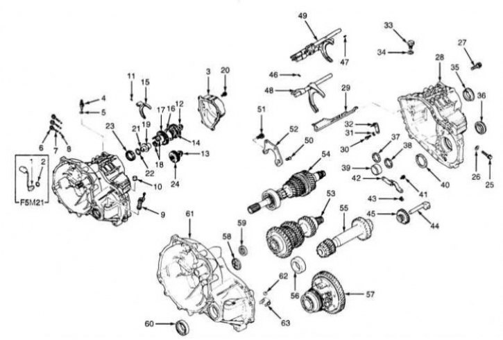
Design of the F5M21 and F5M22 manual transmissions
1 - Transmission switch sensor; 2 - Sealing gasket; 3 - Back cover; 4 - Reverse light switch sensor; 5 - Sealing gasket; 6 - Retainer plug; 7 - Lock spring; 8 - Locking ball; 9 - Speedometer drive assembly; 10 - Manual transmission crankcase ventilation breather; 11 - Spring loaded pin; 12 - Lock nut; 13 - Lock nut; 14 - Assembly of the 5th gear synchronizer; 15 - 5th gear engagement fork; 16 - Synchronizer locking ring; 17 - 5th gear pinion; 18 - Needle bearing; 19 - Bearing sleeve; 20 - End cap bolt; 21 - Retaining ring (selected); 22 - Distance ring (selected); 23 - Roller bearing; 24 - 5th gear intermediate gear; 25 - Reverse gear intermediate gear axle bolt; 26 - Sealing gasket; 27 - Bolt; 28 - Transmission housing; 29 - Oil flow trough; 30 - Bolt; 31 - Spring washer (Grover washer); 32 - Stop bar; 33 - Assembling the ball stop; 34 - Sealing gasket; 35 - Outer ring; 36 - Seal; 37 - Distance ring (selected); 38 - Distance ring (selected); 39 - Outer bearing race; 40 - Distance ring (selected); 41 - Bolt; 42 - Reverse gear engagement lever assembly; 43 - Reverse gear drive assembly shoe; 44 - Reverse intermediate gear shaft; 45 - Reverse intermediate gear; 46 - Spring loaded pin; 47 - Spring loaded pin; 48 - Assembly of the shift rod; 49 - Assembly of the shift rod; 50 - Bolt; 51 - Bolt; 52 - Bearing holder; 53 - Assembling the intermediate gear; 54 - Assembling the primary shaft; 55 - Assembly of the output (secondary) shaft; 56 - Outer bearing race; 57 - Differential assembly; 58 - Oil feed guide; 59 - Seal; 60 - Seal; 61 - Clutch dome; 62 - Magnet; 63 - Magnet holder
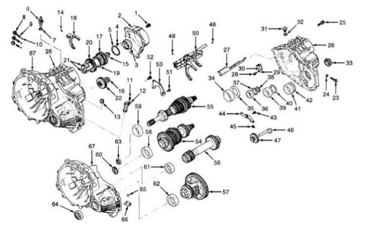
Design of the F5M31/F5M33 manual transmission
1 - Bolt; 2 - Back cover; 3 - Reversible brake cone; 4 - Wave spring; 5 - Self-tapping screw; 6 - Reverse light switch sensor; 7 - Sealing gasket; 8 - Retainer plug; 9 - Lock spring; 10 - Locking ball; 11 - Bolt; 12 - Speedometer drive assembly; 13 - Crankcase ventilation breather; 14 - Spring loaded pin; 15 - Lock nut; 16 - Lock nut; 17 - Assembling the 5th gear synchronizer; 18 - 5th gear engagement fork; 19 - Synchronizer locking ring; 20 - 5th gear pinion; 21 - Needle bearing; 22 - 5th gear intermediate gear; 23 - Reverse gear intermediate gear axle bolt; 24 - Sealing gasket; 25 - Bolt; 26 - Manual transmission housing; 27 - Oil flow trough; 28 - Bolt; 29 - Spring washer (Grover washer); 30 - Stop bar; 31 - Assembling the ball stop; 32 - Sealing gasket; 33 - Seal; 34 - Outer bearing race; 35 - Distance ring (selected); 36 - Outer bearing race; 37 - Distance ring (selected); 38 - Filter (only F5M33); 39 - Outer bearing race (only F5M33); 40 - Distance ring (selectable) (only F5M33); 41 - Outer bearing race; 42 - Distance ring (selected); 43 - Bolt; 44 - Reverse gear engagement lever assembly; 45 - Reverse gear drive assembly shoe; 46 - Reverse intermediate gear shaft; 47 - Reverse intermediate gear; 48 - Spring loaded pin; 49 - Spring loaded pin; 50 - Assembly of the shift rod; 51 - Bolt; 52 - Bolt; 53 - Bearing holder; 54 - Assembling the intermediate gear; 55 - Assembling the primary shaft; 56 - Assembly of the output (secondary) shaft; 57 - Differential assembly; 58 - Outer bearing race; 59 - Outer bearing race; 60 - Oil feed guide; 61 - Outer bearing race; 62 - Outer bearing race; 63 - Seal; 64 - Seal; 65 - Magnet; 66 - Magnet holder; 67 - Clutch dome
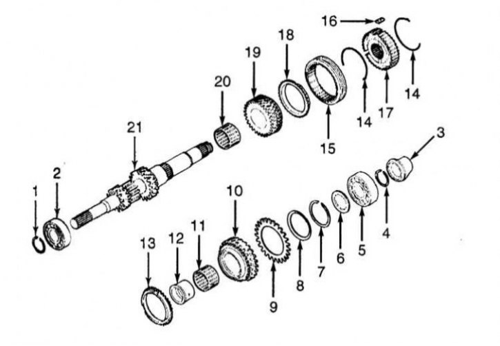
Primary shaft design of manual transmission
1 - Retaining ring; 2 - Ball or tapered bearing; 3 - Bearing sleeve; 4 - Retaining ring (selected); 5 - Ball or tapered bearing; 6 - Distance ring (selected); 7 - Retaining ring (selected); 8 - Cone spring; 9 - Spring loaded toothed ring; 10 - 4th gear pinion; 11 - Needle bearing; 12 - Bearing sleeve; 13 - Synchronizer locking ring; 14 - Synchronizer spring; 15 - 3/4 gear synchronizer sliding clutch; 16 - Sliding synchronizer key; 17 - 3/4 gear synchronizer hub; 18 - Synchronizer locking ring; 19 - 3rd gear pinion; 20 - Needle bearing; 21 - Primary shaft
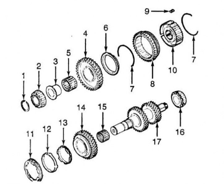
Components of the intermediate shaft assembly of the manual transmission
1 - Retaining ring (selected); 2 - Ball or tapered bearing; 3 - Bearing sleeve; 4 - 1st gear pinion; 5 - Needle bearing; 6 - Synchronizer locking ring; 7 - Synchronizer spring; 8 - Sliding clutch of synchronizer 1/2 gears; 9 - Sliding synchronizer key; 10 - 1/2 gear synchronizer hub; 11 - External synchronizer locking ring (only F5M33); 12 - Synchronizer cone (only F5M33); 13 - Internal synchronizer locking ring; 14 - 2nd gear pinion; 15 - Needle bearing; 16 - Ball or tapered bearing; 17 - Intermediate gear
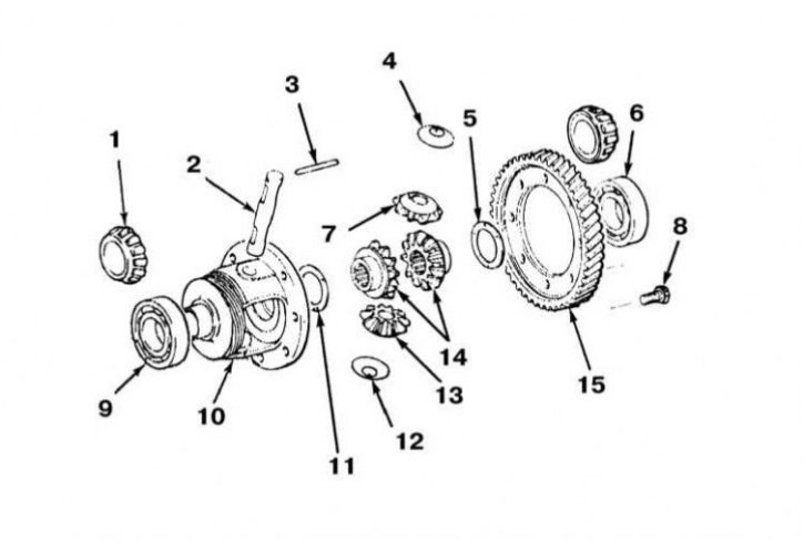
Design of the differential of the main gear of the manual transmission
1 - Tapered roller bearing (F5M22, F5M31/F5M33); 2 - Axle of satellites; 3 - Locking pin; 4 - Washer; 5 - Distance ring (selected); 6 - Ball bearing (F5M21/F5M210); 7 - Satellite; 8 - Bolt; 9 - Ball bearing (F5M21/F5M210); 10 - Differential box; 11 - Distance ring (selected); 12 - Washer; 13 - Satellite; 14 - Side gears; 15 - Driven gear of the main transmission
General information
The authors of this Manual do not recommend that car owners undertake major repairs of the manual transmission on their own. During the procedures of disassembling and assembling the transmission, it is necessary to remove and then install many small components. It is necessary to make a lot of precise measurements and, by selecting adjusting washers, rings and spacer bushings, accurately set many gaps. In view of all the above, it would be wiser to entrust the performance of major repairs of the manual transmission to car service specialists. Note that in many cases it is possible to purchase a reconditioned unit on an exchange basis, which is often cheaper than carrying out complex repairs.
Despite the above, independent repair of the manual transmission by an amateur mechanic is not at all an absolutely impossible undertaking. The only indispensable conditions are the availability of the necessary special tool and accuracy in the approach to performing all procedures.
The tools needed to perform a manual transmission overhaul include circlip pliers, a bearing puller, a sliding hammer, a set of punches and center punches, a DTI dial gauge, and possibly a hydraulic press. Of course, you will also need a sturdy workbench with a vice or a special assembly stand.
When performing the manual transmission disassembly procedures, try to remember, or better yet, write down, the installation order of each of the removed parts.
Before disassembling the gearbox, it would be wise to try to analyze the symptoms of its failures in order to roughly determine their causes. Many failures are clearly associated with the failure of very specific components. See also the Section on diagnosing manual transmission faults at the beginning of the Manual.
Let us take a closer look at three of the gearboxes used in the vehicles discussed in this Manual: F5M31 (Galant), F5M21 (Mirage 1.5 l) and F5M22 (Mirage 1.8 l).
Disassembling the manual transmission
1. The design of the manual transmission is shown in the illustrations.
2. On F5M21 models, remove the transmission switch with its sealing gasket. On all other models, remove the rear cover. Remove the reverse light switch with its sealing gasket. Remove the wave spring, loosen the bolts and remove the reversing brake cone. Unscrew the plugs and take out the retaining springs and balls.
3. Remove the speedometer drive assembly and crankcase breather from the clutch dome. Remove the spring-loaded pin from the 5th gear fork. Chisel the lock nuts of the primary and intermediate shafts.
4. Using the control and selection levers, shift the transmission into reverse gear. Place a split socket wrench with a collar on the primary shaft journal. Screw a 10 mm bolt into the clutch dome and rest the wrench collar against it, thereby blocking the primary shaft from turning. Loosen the lock nut (lock nut).
5. Remove the synchronizer assembly and 5th gear fork. Remove the synchronizer locking ring and 5th gear. On F5M21 models, remove the needle bearing, spacer ring, bearing sleeve, snap ring and roller bearing.
6. On all models, remove the 5th gear idler gear. Remove the reverse gear idler gear shaft bolt and sealing gasket. Remove the transmission housing and oil feed guide. Remove the thrust bar bolt and spring washer. Remove the ball retainer assembly with sealing gasket.
7. On F5M21 models, remove the outer race. On all models, remove the oil seal. On F5M21 models, remove the three spacers and the outer race of one bearing. On all other models, remove the three spacers and the outer races of three bearings.
8. Remove the reverse gear engagement drive lever assembly, the lever assembly shoe, and remove the axle with the reverse gear intermediate gear.
9. Remove the spring-loaded pins of the 1/2 and 3/4 gear shift fork rods. Move the corresponding shift fork to the 2nd gear position, the other fork to the 4th gear position.
10. On F5M21 and F5M22 models, rotate the shift rod assemblies until the shift tabs disengage from the control pin and retainer plate. Pull the rods up to release the ends from the clutch dome. Remove the rods and shift forks.
11. On F5M31/F5M33 models, remove the shift fork rod assembly. On all models, remove the bearing retainer. Raise the input shaft and remove the idler gear assembly.
12. Remove the primary and secondary shaft assemblies. Remove the differential assembly. Remove the outer bearing races from the primary and secondary shafts. If equipped, remove the bearing races from the differential seats in the clutch dome. Remove the oil feed guide and seals from the clutch dome. Remove the magnet with its holder.
5th gear synchronizer
Disassembly
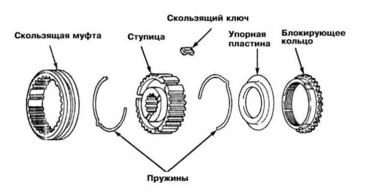
Remove the locking ring, thrust plate, springs, sliding sleeve, sliding keys and synchronizer hub.
Examination
1. Insert the synchronizer hub into the coupling and manually check the free rotation of the components. Inspect the coupling for signs of wear or damage to the front and rear inner edges. Inspect the condition of the hub mating surface with the fifth gear pinion. Assess the degree of wear on the upper projections of the sliding keys. Inspect the springs for signs of weakening, deformation, cracks and other mechanical damage.
2. Replace defective components.
Note: The sliding sleeve is replaced together with the hub.
Assembly
1. Insert the hub with the sliding keys installed into the synchronizer sleeve - make sure that the components are correctly engaged.
2. Install the springs so that the sliding keys rest against their ledges. Make sure that the springs are turned with the locks in different directions.
3. Finally, install the thrust plate and locking ring.
Primary shaft of the F5M21 manual transmission
Disassembly
1. The design of the primary shaft assembly is shown in the illustration.
2. Remove the retaining ring and dismantle the front bearing from the shaft journal.
3. Remove the inner ring (rear bearing), spacer ring and 4th gear.
4. Remove the 3rd gear pinion, 3/4 synchronizer assembly and bearing sleeve.
Examination
1. Assess the degree of wear of the bearing surfaces and shaft splines. Install the needle bearing on the shaft and check its tightness and freedom of rotation. Make sure that there are no deformations of the bearing housing.
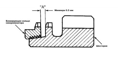
2. Check the integrity of the synchronizer locking ring teeth. Make sure there are no signs of damage and the integrity of the threads on the inner surface. Press the synchronizer ring toward the gear and measure the gap between the components. If the measurement result exceeds 0.5 mm, replace the locking ring.
3. Insert the synchronizer hub into the clutch and check the freedom of movement of the components relative to each other. Check the condition of the front and rear edges of the clutch, assess the degree of wear of the mating surface of the hub with the gear and the working projections of the sliding keys. Check the condition of the synchronizer springs.
4. Replace defective components.
Note: The sliding sleeve is replaced together with the hub.
5. Check the smoothness of the synchronizer cone surface. Assess the condition of the front and rear mating surfaces. Make sure that the teeth of all gears are intact.
Assembly
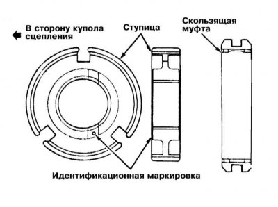
1. Assembly is performed in the reverse order of dismantling the components. Place the synchronizer hub (marked side first) into the sliding clutch. Ensure that the components are correctly aligned - the central tooth of the hub must fit between the two missing teeth of the clutch and engage with the sliding key.
2. Install the synchronizer springs so that the sliding keys rest against their protruding sections. Make sure that the springs are turned with the locks in different directions.
3. Place the 3/4 gear synchronizer assembly onto the shaft.
Note: Make sure that the sliding keys fit into the grooves in the locking ring, check the freedom of rotation of the 3rd gear pinion.
4. Using a special device, seat the bearing sleeve on the shaft. Install the spacer ring (identification mark "1" towards the 4th gear).
Note: If there is no marking, the ring can be seated arbitrarily. Seat the inner ring (rear bearing) on the shaft.
The article is based on data from the website mitsubishiman
5. Using a special tool, seat the front bearing on the shaft and insert a new retaining ring into the groove.
Note: Retaining rings are available in different thicknesses - select the largest that fits in the groove.
Be careful not to damage the surface of the shaft journal that contacts the seal.
Primary shaft of manual transmission F5M22 and F5M31/F5M33
Disassembly
1. Remove the retaining ring and dismantle the front bearing from the shaft journal. Remove the rear bearing, spacer ring and 4th gear with bearing.
2. Remove the bearing sleeve, 3/4 synchronizer assembly and 3rd gear.
3. Remove the needle bearing.
Examination
1. Assess the degree of wear of the bearing surfaces and shaft splines. Install the needle bearing on the shaft and check its tightness and freedom of rotation. Make sure that there are no deformations or damage to the bearing housing.
2. Check the integrity of the synchronizer locking ring teeth. Make sure there are no signs of damage and the integrity of the inner surface of the threads applied to it. Press the synchronizer ring toward the gear and measure the gap between the components. If the measurement result exceeds 0.5 mm, replace the locking ring.
3. Insert the synchronizer hub into the sliding clutch and check the freedom of movement of the components relative to each other. Check the condition of the front and rear edges of the clutch, assess the degree of wear of the mating surface of the hub with the gear and the working projections of the sliding keys. Check the condition of the synchronizer springs.
4. Replace defective components.
Note: The sliding sleeve is replaced together with the hub.
5. Check the smoothness of the synchronizer cone surface. Assess the condition of the front and rear mating surfaces. Make sure that the teeth of all gears are intact.
Assembly
1. Place the synchronizer hub (marked side first) into the sliding sleeve. Make sure the components are correctly aligned - the central tooth of the hub must fit between the two missing teeth of the sleeve and engage with the sliding key.
2. Install the synchronizer springs so that the sliding keys rest against their protruding sections. Make sure that the springs are turned with the locks in different directions.
3. Place the 3/4 gear synchronizer assembly onto the shaft.
Note: Make sure that the sliding keys fit into the grooves in the locking ring, check the freedom of rotation of the 3rd gear pinion.
4. Using a special device, seat the bearing sleeve on the shaft. Install the spacer ring (identification mark "1" towards the 4th gear).
Note: If there is no marking, the ring can be seated arbitrarily. Seat the rear bearing with the sleeve.
5. Using a special tool, seat the front bearing on the shaft and insert a new retaining ring into the groove.
Note: Retaining rings are available in different thicknesses - select the largest that fits into the groove. Try not to damage the surface of the shaft journal that contacts the seal.
Intermediate shaft
Disassembly
1. The design of the intermediate shaft assembly is shown in the illustration.
2. Remove the retaining ring and dismantle the bearing with the coupling from the shaft.
3. Remove the needle bearing and 1st gear.
Note: The bearing must be replaced without fail.
4. Remove the 1/2 gear synchronizer assembly, 2nd gear gear and needle bearing from the shaft.
5. Remove the rear bearing assembly.
Examination
1. Assess the degree of wear of the bearing surfaces of the assembly. Install the needle bearing on the shaft and check its tightness and freedom of rotation. Make sure that there are no deformations or damage to the bearing housing.
2. Check the integrity of the synchronizer locking ring teeth. Make sure there are no signs of damage and the integrity of the inner surface of the threads applied to it. Press the synchronizer ring toward the gear and measure the gap between the components. If the measurement result exceeds 0.5 mm, replace the locking ring.
3. Insert the synchronizer hub into the sliding clutch and check the freedom of movement of the components relative to each other. Check the condition of the front and rear edges of the clutch, assess the degree of wear of the mating surface of the hub with the gear and the working projections of the sliding keys. Check the condition of the synchronizer springs.
4. Replace defective components.
Note: The sliding sleeve is replaced together with the hub.
5. Check the smoothness of the synchronizer cone surface. Assess the condition of the front and rear mating surfaces. Make sure that the teeth of all gears are intact.
Assembly
1. Assembly is performed in the reverse order of dismantling the components. Using a special device, seat the bearing on the shaft - make sure that the tool mandrel rests only on the end surface of the inner bearing race.
2. Place the 1/2 gear synchronizer hub (marked side first) into the sliding sleeve. Make sure the components are correctly aligned - the center tooth of the hub must fit between the two missing teeth of the sleeve and engage with the sliding key.
3. Install the synchronizer springs so that the sliding keys rest against their protruding sections. Make sure that the springs are turned with the locks in different directions.
4. Place the 1/2 gear synchronizer assembly onto the shaft.
5. Using a special device, seat the bearing sleeve on the shaft. Install the 1st gear pinion with the bearing sleeve, and finally seat the bearing on the shaft.
Exhaust (secondary) shaft
1. The secondary shaft assembly structure is shown in the illustrations.
2. Remove the bearings from the shaft - they must be replaced during assembly; the inner and outer races are replaced as a set. Assess the condition of the shaft and the degree of wear of its working components. Install new bearings on the shaft. Assembly is performed in the reverse order.
Gear shift forks
1. Remove the 1.2 gear shift fork. Remove the shift rod assembly.
2. Remove the 3/4 shift fork assembly and the 5th/reverse shift rod. Remove the 3/4 shift fork rod. Remove the reverse shift dog.
3. Reassemble in reverse order. Make sure the plunger of the locking pin enters the reverse gear shift dog in the groove of the 3/4 gear rod.
Final drive differential
Disassembly and checking of the components
1. The differential design is shown in the illustration.
2. Unscrew the mounting bolts and remove the driven gear of the reverse gear. Press the bearings out of the differential box - during assembly, the bearings must be replaced without fail.
3. Remove the locking pin from the side of the driven gear mounting flange. Release the axle and satellite gears from the box, remove the washers and remove the side gears.
4. Carefully inspect all components for signs of excessive wear and mechanical damage. Replace defective elements.
Assembly
1. Place the spacer rings on the rear of the side gears and install the latter into the differential box. Insert both satellites into the differential box. Install the satellite axle.
2. Measure the amount of play between the satellites and the side gears. If the measurement result is outside the permissible range (0.025÷0.150 mm), disassemble the differential and select spacer rings of the required thickness.
Note: When installing new side gears, they should be equipped with identical spacer rings of medium thickness (0.93÷1.00 mm).
3. Secure the satellite axle with a new locking pin.
Note: The pin should not protrude above the differential case surface by more than 3 mm.
4. Press new bearings into the differential case.
Attention! The tool mandrel must rest only against the inner bearing race!
5. Before screwing in used driven gear mounting bolts, run a tap of the appropriate size through their threads to remove traces of corrosion/old sealant and restore damaged threads, then lubricate the bolts with fresh locking sealant. Tighten the bolts with the required force (130÷140 N·m) in a diagonal order.
Assembly of manual transmission
Note: The spacers used to set the preload and the retaining rings are subject to selection.
1. Assembly is carried out in the reverse order of dismantling the components.
2. Install the drive and primary shaft seals. At the same time, insert the intermediate and primary shaft assemblies into the transmission housing.
3. Lubricate the primary shaft bearing mounting bolt closest to the differential with 3M STUD (4170) type locking sealant - try not to let the sealant get on the bolt head. Screw in the bolts and tighten them to the required torque (16÷22 N·m).
4. Place the 1/2 gear shift clutch into the 2nd gear pinion, and the 3/4 gear shift clutch into the 4th gear pinion, respectively. Engage the shift assembly forks with the grooves in the clutches. Insert the fork rods into the corresponding holes in the clutch dome and turn them to engage the pawls with the control pin and locking plate.
5. Using a suitable punch, seat the new spring pins (cut along the rod axis). Install the intermediate gear axis (with the threaded hole in the head facing the differential).
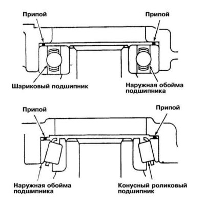
6. Place two pieces of solder, 10 mm long and 1.6 mm in diameter, in place of the spacer rings.
7. Install the transmission case and tighten the bolts to the required torque. Remove the bolts again, remove the case, dismantle the outer bearing races and remove the flattened solder. Measure the thickness of the solder with a micrometer and select the appropriate spacers, this procedure will allow you to correctly select the axial play of the components (see Specifications).
8. Install the oil feed guide into the transmission housing. Put the spacers of the selected thickness on the intermediate gear assembly, then install the outer race of the differential bearing. Install the spacers of the appropriate thickness between the outer race of the bearing and the gearbox housing. Make sure that the reverse intermediate gear shaft is turned with the threaded hole in the head in the correct direction, then you can proceed to install the gearbox housing.
9. Apply a 1.0÷2.0 mm thick bead of sealant evenly to the surface of the crankcase mating with the clutch dome (use Mitsubishi MD997740 or Three Bond 1216 sealant). Press the crankcase to the dome.
10. Using a punch (Phillips screwdriver) with a diameter of 8.0 mm, align the threaded hole in the axle of the intermediate gear of the reverse gear with the corresponding bolt hole in the transmission housing. Screw in the bolt and tighten it with the required force (43÷55 N·m). Tighten the other transmission housing mounting bolts with the required force.
11. If the assembly is appropriate, select a retaining ring of the appropriate thickness for the size of the mounting groove - retaining rings must be replaced in the required order. Place the retaining ring on the primary shaft journal. Check the tightness of the coupling flange against the bearing.
12. Install the 5th gear fork (included with the synchronizer). Lock the shaft from turning using a socket wrench with a slotted head and a 10 mm bolt screwed into the clutch dome.
13. Using the control and selection levers, shift the manual transmission to reverse gear. Screw on new lock nuts, tighten them to the required force (140÷160 N·m) and calk.
14. Install a new 5th gear shift fork spring (cut along the rod axis).
15. Apply 3M Super Weatherstrip (8001) sealant to the air breather mounting surface and install the clutch dome. Install the rear clutch dome cover, having first applied a uniform bead of sealant (such as Mitsubishi MD997740 or Tree Bound 1216) 1-2 mm thick to its mating surface.
16. Install the manual transmission assembly onto the engine (see Section Removal and installation the gearbox).