



Contents: Road tests (road test) ⤓ Table. Checking the voltage at the…⤓ Checking the automatic transmission…⤓ Checking on a fully braked vehicle…⤓ Checking the pressure in the…⤓ Table. Checking nominal pressures in…⤓ Main line pressure adjustment ⤓
Road tests (road test)
Before performing a road test, make sure that basic checks have been performed, including checking the level and condition of the automatic transmission fluid and adjusting the automatic transmission control cable.
1. Turn the ignition key from the "OFF" position to the "ON" position and check the serviceability of the automatic transmission control relay (presence of on-board voltage).
2. With the ignition switch in the "ON" position, the engine not running and the automatic transmission selector in the "P" position, do the following:
a) Move the automatic transmission selector to positions "R", "N", "D", "3", "2", "L". Check the serviceability of the start inhibit switch (correspondence between the selector position and the switch signal).
b) Check the throttle position sensor for proper operation:
- When the accelerator pedal is released (535 - 735 mV).
- When pressed to half the stroke (smoothly increases from the value of 535 mV).
- When the accelerator pedal is fully depressed (4500 - 5000 mV).
3. Move the automatic transmission selector to the "P" or "N" position. Set the ignition key to the "START" position (engine not running) and make sure that starting the engine (cranking the crankshaft with the starter) is only possible in the specified selector positions.
4. Drive the car for 15 minutes or more and check the serviceability of the automatic transmission fluid temperature sensor (the automatic transmission fluid temperature gradually increases to 70 - 80°C).
5. With the engine idling and the automatic transmission selector in position "N", perform the following checks:
a) When the air conditioner switch is in the "ON" or "OFF" position, check that the dual refrigerant pressure switch is functioning properly.

Table. Checking the voltage at the terminals of the electronic control unit of the engine and automatic transmission.
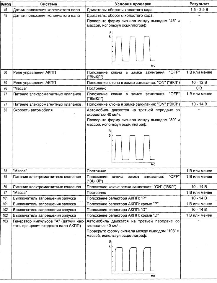
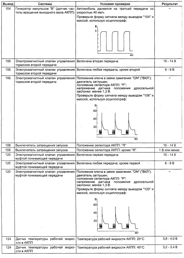
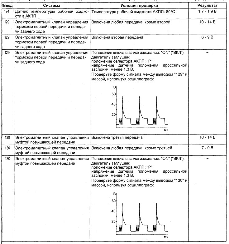
6) Check the crankshaft position sensor and the connection with the engine control unit when the accelerator pedal is released (the tachometer readings correspond to the tester readings) and pressed to half the stroke (smoothly increases).
c) When moving the automatic transmission selector from position "N" to "D" and from "N" to "R", make sure that there are no faults when starting to move (there should be no sharp jolts when changing gears, the gear engagement time should not exceed 2 seconds).
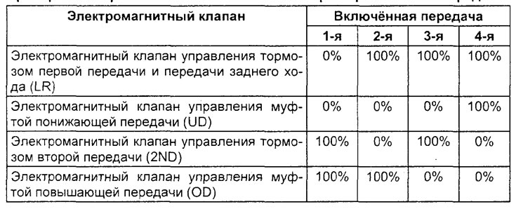
6. Check that the gears being engaged correspond to the specified speed and check the condition of the electromagnetic valves. The check is performed on a straight horizontal section of the road, the initial position of the selector: "N" (see the table "Checking the electromagnetic valves of the automatic transmission when shifting gears"). The following conditions must be met for 10 seconds or longer.
Checking the automatic transmission electromagnetic valves when shifting gears.
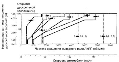
Automatic transmission operation diagram.
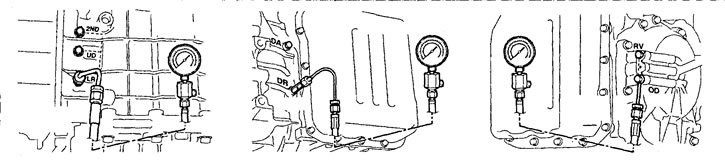
Holes for measuring pressure in the lines of the hydraulic control system of the automatic transmission. 2ND - second gear brake, UD - downshift clutch, LR - first gear and reverse gear brake, DR - torque converter outlet pressure, DA - torque converter inlet pressure, RV - reverse gear clutch, 0D - overdrive clutch.
a) The engine is idling (selector in position "L"; the car is braked).
b) The car moves at a constant speed of 10 km/h (in 1st gear).
c) The car moves at a constant speed of 20 km/h (in 2nd gear).
d) The car moves at a constant speed of 40 km/h (in 3rd gear).
d) The car moves at a constant speed of 50 km/h (in 4th gear).
7. Under the conditions specified in paragraph 6, items "a" and "d", check the serviceability of the vehicle speed sensor (0 km/h and 50 km/h, respectively).
8. Under the conditions specified in paragraph 6 of subparagraph "g", check the serviceability of the automatic transmission input shaft speed sensor and the automatic transmission output shaft speed sensor (nominal value).
Nominal value - 1400 - 1700 rpm
9. Perform the test with the automatic transmission selector in the "D" position and the vehicle moving on a straight horizontal section of the road. Make sure that there are no faults when shifting gears (e.g. the gear does not engage or does not shift from one gear to another) and that there is no shifting of gear shift moments. Use the tester to stop operation in the INVECS-II mode.
a) Accelerate the vehicle to 4th gear with a throttle position sensor signal voltage of 1.5 V (throttle valve open 25%).
b) Brake smoothly until the car stops.
c) Accelerate the vehicle to 4th gear with a throttle position sensor signal voltage of 2.5 V (throttle valve open 50%).
d) Accelerate the car from 1st to 4th gear.
d) When driving in 4th gear at a speed of 45 km/h, shift to 3rd gear (move the automatic transmission selector to position "3").
e) When driving in 3rd gear at a speed of 25 km/h, shift to 2nd gear (move the automatic transmission selector to position "2").
g) When driving in 2nd gear at a speed of 15 km/h, shift to 1st gear (move the automatic transmission selector to the "L" position).
Note:
- When checking points "a", "b" and (c), the read values should correspond to the nominal value of the speed of the output shaft of the automatic transmission (vehicle speed) and no sharp jolts should be felt.
- When checking items "g", "d", "e" and "g", switching to a lower gear should occur immediately after moving the automatic transmission selector.
10. Move the automatic transmission selector from the "N" position to the "R" position and check that the reverse gear is engaged. When the vehicle is moving at a speed of 5 km/h on a straight horizontal section of the road, check that the ratio between the values of the signals of the automatic transmission input shaft speed sensor and the automatic transmission output shaft speed sensor is equal to the gear ratio with the reverse gear engaged.
Checking on a fully braked vehicle (stall test)
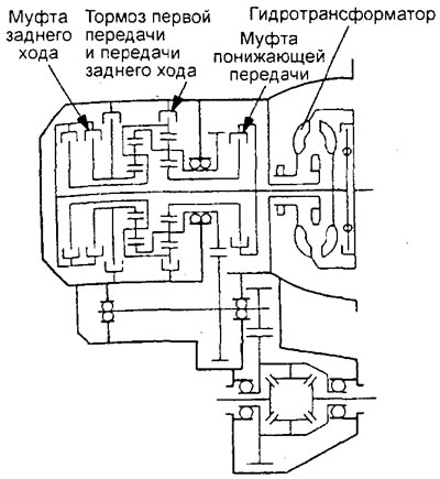
The purpose of this test is to measure the maximum engine crankshaft speed with the gearbox output shaft fully braked in the "D" and "R" ranges. The value of this speed can be used to determine the operability of the torque converter stator overrunning clutch, as well as the presence of slippage in the friction clutches and the brake in first gear and reverse gear.
Attention:
- Do not allow anyone to be in front or behind the vehicle during this check.
- The test should be carried out by two technicians: one should observe the wheels outside the car, and the other should carry out the test itself inside the car.
- The duration of each check should not exceed 5 seconds.
1. Measuring the speed of a fully braked vehicle:
(The text of the article was obtained from the website: «MitsubishiMan.ru»)
- a) Check the level and temperature of the working fluid in the automatic transmission, as well as the temperature of the engine coolant. The working fluid of the automatic transmission must be warmed up to normal operating temperature (70 - 80°C). The level of the working fluid must be in the "HOT" range of the dipstick. The engine coolant must also be warmed up to normal operating temperature (80 - 100°C).
- b) Place chocks under the rear wheels of the vehicle.
- c) Apply the parking brake and press the brake pedal all the way down.
- d) Start the engine.
- d) Move the selector to position "D". Press the accelerator pedal all the way down. Quickly read the tachometer readings and compare them with the nominal values.
Attention:
- During this test, do not hold the accelerator pedal fully depressed longer than necessary to determine maximum engine speed or more than eight seconds.
- If this test needs to be performed more than once, after each test, move the automatic transmission selector to the "N" position and let the engine run at 1000 rpm to cool the working fluid in the automatic transmission between tests.
The nominal value of the engine crankshaft speed with the vehicle fully braked (selector in position "D") is 2200 - 2700 rpm
e) Repeat the test with the selector in the "R" range.
The nominal value of the engine crankshaft speed with the vehicle fully braked (selector in position "D") is 2200 - 2700 rpm
2. Analysis of the test results on a fully braked vehicle.
a) If the engine crankshaft speed is higher than the nominal value when the selector is in position "D" or "R", the cause may be:
- torque converter slip;
- low pressure in the main line;
- first gear and reverse gear brake slippage.
b) If the engine crankshaft speed is greater than the nominal value when the selector is in position "D", the cause may be:
- downshift clutch slippage.
c) If the engine crankshaft speed is less than the nominal value when the selector is in the "R" position, the cause may be:
- reverse gear clutch slippage.
d) If the engine crankshaft speed is less than the nominal value when the selector is in position "D" or "R", the cause may be:
- torque converter failure;
- malfunction of the electronic engine control unit.
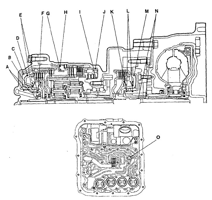
Location of automatic transmission seals.
Checking the pressure in the automatic transmission hydraulic control system (hydraulic test)
Note: checking the pressure in the automatic transmission control hydraulic system is the main one for determining the causes of automatic transmission malfunction. Before doing it, perform basic checks and adjustments (check the level of the working fluid in the variator and its condition, etc.). Checking the pressure in the hydraulic system should be carried out at normal temperature of the variator working fluid (70 - 80°C).
1. Checking the pressure in the lines.
a) Warm up the automatic transmission fluid to operating temperature (70 - 80°C).
b) Place chocks under the rear wheels of the vehicle.
c) Apply the parking brake and press the brake pedal all the way down.
d) Start the engine.
d) Connect the adapter to the appropriate hole, connect the tubes and pressure gauge.
Note: When checking pressure, use a pressure gauge with a measurement range of 3000 kPa.
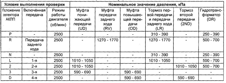
e) Make sure that the obtained data corresponds to the nominal values (see the table "Checking the nominal pressures in the automatic transmission control hydraulic system").
Table. Checking nominal pressures in the automatic transmission control hydraulic system.
2. Analysis of the results of checking the pressure in the hydraulic system of the variator control.
a) High pressure in all lines can be caused by:
- pressure regulator malfunction.
b) Low pressure in all lines can be caused by:
- malfunction of the working fluid pump;
- malfunction of the working fluid filter;
- malfunction of the working fluid cooler;
- electromagnetic valve malfunction;
- malfunction of sealing rings;
- incorrect installation of each of the solenoid valves.
- incorrect installation of the solenoid valve block.
c) Incorrect pressure only in the "R" (reverse) range can be caused by:
- malfunction of the switching valve,
- pressure regulator malfunction.
d) Incorrect pressure only in 3rd or 4th gear may be caused by:
- pressure regulator malfunction.
d) Inadequate pressure only in the underdrive clutch (UD) line can be caused by:
- defect of the seal "K", "L" or "M",
- malfunction of the electromagnetic valve controlling the downshift clutch,
- malfunction of the pressure control valve in the downshift clutch line, malfunction of the ball valve,
- clogging of the main line;
- incorrect installation of the solenoid valve block.
e) Inadequate pressure in the reverse clutch (RV) line only may be caused by:
- defect of the seal "A", "B" or "C",
- ball valve malfunction,
- clogging of the main line;
- incorrect installation of the solenoid valve block.
g) Inadequate pressure in the overdrive clutch line only (OD) can be caused by:
- seal defect "D", "E" or "F"
- malfunction of the electromagnetic valve controlling the overdrive clutch,
- malfunction of the pressure control valve in the overdrive clutch line,
- ball valve malfunction,
- clogging of the main line;
- incorrect installation of the solenoid valve block.
c) Inadequate pressure; only in the brake line of the first gear and reverse gear (LR) can the following be caused:
- defect of the seal "1" or "J",
- malfunction of the electromagnetic valve controlling the brake of the first gear and reverse gear,
- malfunction of the pressure regulation valve in the brake line of the first gear and reverse gear,
- malfunction of the switching valve,
- ball valve malfunction,
- malfunction of the emergency mode valve "A",
- clogging of the main line;
- incorrect installation of the solenoid valve block.
i) Incorrect pressure only in the second gear brake line (2ND) may be caused by:
- defect of the seal "G", "H" or "O",
- malfunction of the electromagnetic valve controlling the second gear brake,
- malfunction of the pressure control valve in the second gear brake line,
- malfunction of the emergency mode valve "B",
- clogging of the main line;
- incorrect installation of the solenoid valve block.
k) Inadequate pressure only in the torque converter (DR) feed line can be caused by:
- malfunction of the automatic transmission fluid cooler,
- malfunction of the "N" seal,
- malfunction of the pressure control valve in the torque converter lock-up clutch line,
- clogging of the main line;
- incorrect installation of the solenoid valve block.
l) Inadequate pressure only in the torque converter feed line (DR) can be caused by:
- incorrect adjustment of the automatic transmission control cable;
- malfunction of the manual range selection solenoid valve;
- incorrect installation of the solenoid valve block.
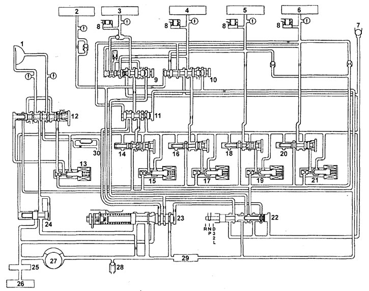
Hydraulic diagram of the automatic transmission control system. 1 - torque converter lock-up clutch, 2 - reverse clutch, 3 - first gear and reverse brake, 4 - second gear brake, 5 - downshift clutch, 6 - upshift clutch, 7 - ball valve, 8 - hydraulic accumulator, 9 - emergency mode valve "A", 10 - emergency mode valve "B", 11 - changeover valve, 12 - torque converter lock-up clutch control valve, 13 - torque converter lock-up clutch control electromagnetic valve, 14 - first gear and reverse clutch line pressure regulating valve, 15 - first gear and reverse brake control electromagnetic valve, 16 - second gear brake line pressure regulating valve, 17 - second gear brake control electromagnetic valve, 18 - downshift clutch line pressure regulating valve, 19 - downshift clutch control electromagnetic valve, 20 - line pressure regulating valve overdrive clutch, 21 - electromagnetic valve for controlling the overdrive clutch, 22 - manual range selection valve, 23 - pressure regulator, 24 - torque converter pressure regulating valve, 25 - oil filter, 26 - oil pan, 27 - variator working fluid pump, 28 - safety valve, 29 - mesh filter, 30 - lubrication system line.
Main line pressure adjustment
1. Drain the automatic transmission fluid and remove the control solenoid valve block cover.
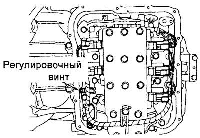
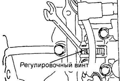
2. Turn the pressure regulator adjusting screw and adjust the pressure in the underdrive clutch (UD) line so that it corresponds to the nominal value. Turning the pressure regulator adjusting screw clockwise decreases the line pressure, and turning it counterclockwise increases the line pressure.
Nominal value - 1010 - 1050 kPa
Attention: when the adjusting screw is turned by 1 revolution, the pressure of the working fluid in the automatic transmission hydraulic system changes by 35 kPa.
3. Install the control solenoid valve block cover back into place.
4. Fill the automatic transmission with working fluid.
5. Check the pressure in the automatic transmission control hydraulic system. Repeat the pressure adjustment if necessary.