



Contents: Removal ⤓ Installation ⤓
Removal
− Before you begin removing parts, perform the following operations:
- a) Remove the lower protective cover of the power unit.
- b) Drain the working fluid from the automatic transmission (see chapter "Maintenance and general check and adjustment procedures").
- c) Drain the coolant (see chapter "Maintenance and general check and adjustment procedures").
- d) Remove the engine casing (see chapter "Engine - mechanical part").
- d) Remove the battery and battery bracket.
- e) Remove the exhaust system components (see chapter "Intake and exhaust systems").
− The parts are removed in the order of the numbers indicated in the figure "Removing the variator assembly".
− To remove some elements or to disconnect them from other parts, use the relevant chapters:
- starter - see chapter "Engine starting system";
- drive shafts - see chapter "Drive shafts and axle shafts";
- lower arm of the front suspension and anti-roll bar - see chapter "Suspension";
- wheel speed sensor - see chapter "Brake system".
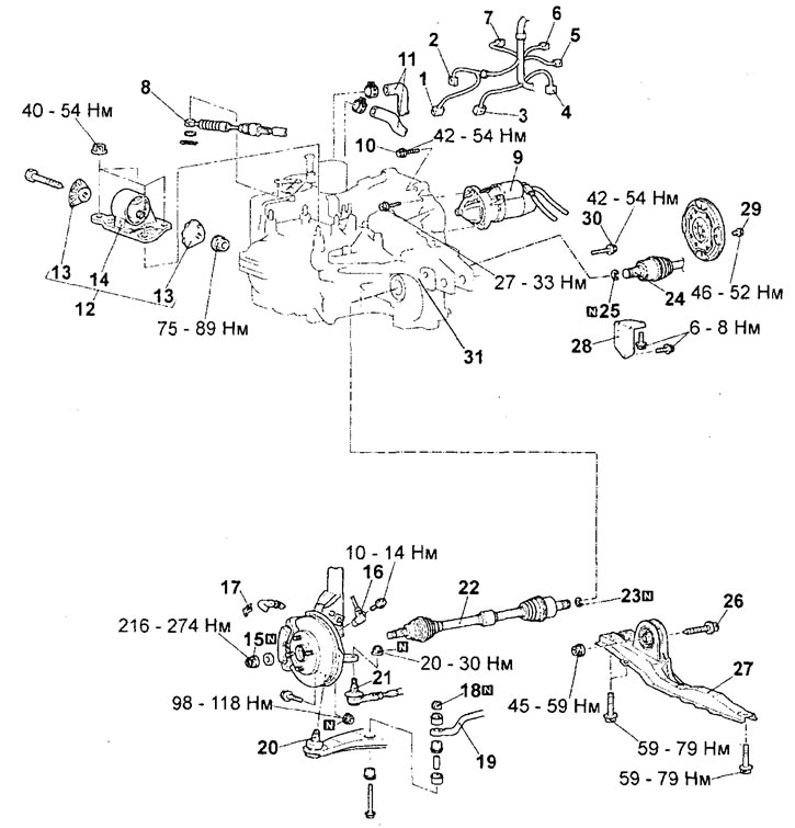
Removal the gearbox assembly. 1 - CVT control solenoid valve connector, 2 - starter inhibit switch connector, 3 - automatic transmission input shaft speed sensor connector, 4 - automatic transmission output shaft speed sensor connector, 5 - knock sensor connector, 6 - coolant temperature sensor connector, 7 - working fluid temperature gauge connector, 8 - automatic transmission control cable connection (from the automatic transmission side), 9 - starter, 10 - automatic transmission bracket bolt, 11 - coolant hoses, 12 - automatic transmission support, 13 - support stopper, 14 - support, 15 - drive shaft lock nut, 16 - wheel speed sensor, 17 - brake hose retainer, 18 - stabilizer mounting nut, 19 - anti-roll bar, 20 - ball joint of the lower arm of the front suspension, 21 - steering tip rods, 22 - left drive shaft, 23 - retaining ring, 24 - right drive shaft, 25 - retaining ring, 26 - cross beam bolt, 27 - cross beam, 28 - lining, 29 - bolt, 30 - mounting bolt, 31 - gearbox assembly.
Note: The nut securing the gearbox to the cross member should first be tightened only preliminarily, and the final tightening to the specified torque should be performed after the gearbox has been completely lowered onto the supports.
Installation
− Installation of parts is carried out in the reverse order of removal.
- When installing parts, pay attention to the following operations:
1. Installing the gearbox assembly. Move the torque converter fully toward the gearbox until the value "A" shown in the figure matches the nominal value, then install the CVT assembly onto the engine.
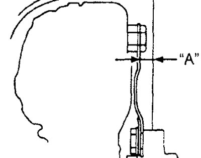
Size "A" - 12.2 mm
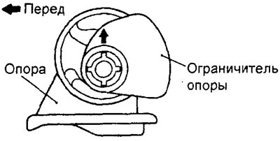
2. Gearbox support limiter.
Install the gearbox support limiter so that the arrow on the limiter is positioned as shown in the figure.
- After completing the installation of the parts, perform the following operations:
a) Install the exhaust system components (see chapter "Intake and exhaust systems").
b) Install the battery and battery bracket.
c) Install the engine casing (see chapter "Engine - mechanical part").
d) Fill with coolant (see chapter "Maintenance and general check and adjustment procedures").
d) Fill the automatic transmission with working fluid (see chapter "Maintenance and general check and adjustment procedures").
e) Install the lower protective cover of the power unit.
g) (4WD models) Install the transfer case (see section "Transfer case assembly").
c) Perform the following checks and adjustments (see section "Checking the automatic transmission control system"):
- check and, if necessary, adjust the engine start inhibit switch and automatic transmission control cable;
- check the operation of the automatic transmission selector;
- check and, if necessary, adjust the ignition lock mechanism;
- check and, if necessary, adjust the automatic transmission selector lock system;
- if necessary, adjust the automatic transmission control cable.