



Contents: Table. Checking the switch. ⤓ Table. Checking electromagnetic…⤓ Note: Replace the solenoid valve…⤓ Table. Nominal values. ⤓ Adjusting the automatic transmission…⤓ Table. Checking the switch. ⤓ Checking the operation of the…⤓ Checking and adjusting the ignition…⤓ Checking and adjusting the automatic…⤓
Note:
- The throttle position sensor and crankshaft position sensor testing procedures are provided in the chapter "Fuel injection system".
- The procedure for checking the vehicle speed sensor is given in the chapter "Body electrical equipment".
- The procedure for checking the dual pressure switch or triple pressure switch (load signal from the air conditioner compressor) is given in the chapter "Heater, air conditioner and ventilation system".
- The procedure for checking the brake light switch is given in the chapter "Brake system".
- The detailed procedure for checking the engine start inhibit switch is given in the section "Checking and adjusting the engine start prohibition switch and automatic transmission control cable".
1. Checking the start inhibit switch.
Check the start inhibit switch circuit according to the table below.
Table. Checking the switch.
| Selector position | The circuit is closed between the terminals |
| R | 3-8 and 9-10 |
| R | 7-8 |
| N | 4-8and9-10 |
| D | 1 -8 |
| 1 | 5-8 |
| 2 | 2-8 |
| 3 | 6-8 |
2. Checking the automatic transmission control relay.
a) Remove the relay.
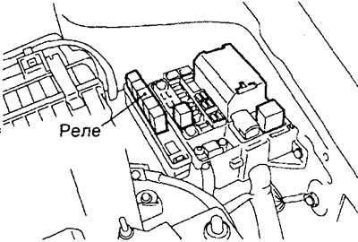
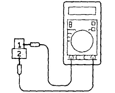
b) Connect the voltmeter and power source as shown in the figure.
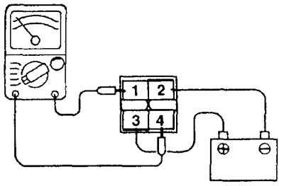
c) When connecting and disconnecting the power source wire, check the conductivity between terminals "1" and "4" of the connector.
| Power supply | Conductivity |
| Connected | Eat |
| Disconnected | No |
d) Replace the relay if necessary.
3. Checking the electromagnetic valves.
a) Disconnect the solenoid valve block connector.
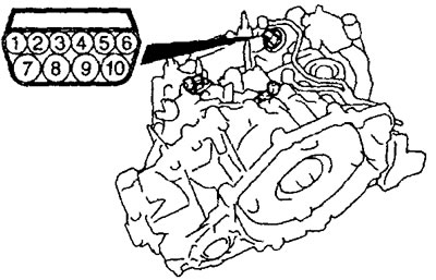
b) Bring the working fluid temperature to 20°C and measure the resistance at the terminals of the electromagnetic valve block connector (see the table "Checking electromagnetic valves").
c) If the obtained values do not correspond to the technical data, check the power supply and ground circuit and eliminate possible faults.
d) If the above steps do not resolve the problem, check each solenoid valve.
- Remove the solenoid valve block cover.
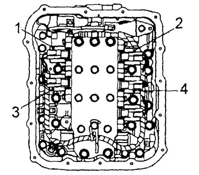
Block of electromagnetic valves. 1 - electromagnetic valve for controlling the upshift clutch, 2 - electromagnetic valve for controlling the downshift clutch, 3 - electromagnetic valve for controlling the first gear brake and reverse gear, 4 - electromagnetic valve for controlling the second gear brake.
- Measure the resistance at the terminals of the connectors of each solenoid valve.
Nominal resistance (at 20°C) — 2.7 - 3.4 Ohm
- If the measured resistance does not correspond to the nominal value, check the wiring and valve sealing rings, and then repeat the test.
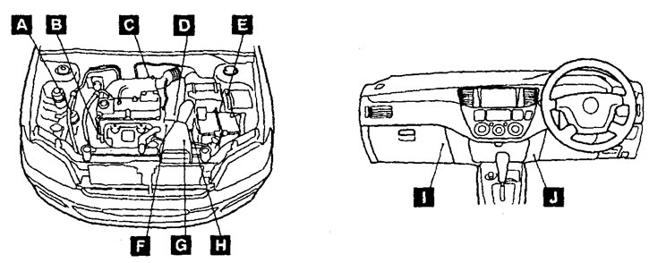
Location of automatic transmission control system components. A - Double switch for refrigerant pressure; B - crankshaft position sensor; C - throttle position sensor with built-in sensor-switch for fully closed throttle position, D - automatic transmission output shaft speed sensor (pulse generator "B"); E - automatic transmission control relay; F - automatic transmission input shaft speed sensor (pulse generator "A"); G - start inhibit switch; H - automatic transmission fluid temperature sensor and automatic transmission control solenoid valves; I - electronic control unit for engine and automatic transmission, J - diagnostic connector.
Table. Checking electromagnetic valves.
| Pin numbers | Valve name | Nominal resistance |
| 6-10 | Solenoid valve for controlling the brake of the first gear and reverse gear | 2.7-3.4 Ohm |
| 4-9 | Second gear brake solenoid valve | 2.7-3.4 Ohm |
| 3-9 | Solenoid valve for controlling the downshift clutch | 27-3.4 Ohm |
| 5-9 | Overdrive clutch control solenoid valve | 2.7 - 3.4 Ohm |
- If the measured resistance still does not match the nominal value, replace the faulty solenoid valve.
Note: Replace the solenoid valve block assembly if necessary.
4. Checking the automatic transmission fluid temperature sensor.
a) Remove the sensor.
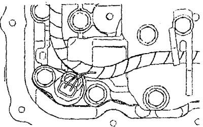
b) Using an ohmmeter, measure the resistance between terminals "1" and "2" of the sensor connector at different temperatures of the working fluid.
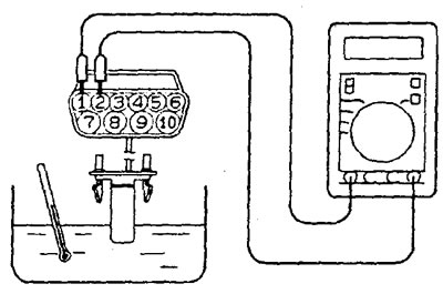
Table. Nominal values.
| Temperature | Resistance |
| 0°C | 16.70 - 20.50 kOhm |
| 20°C | 7.30 - 8.90 kOhm |
| 40°C | 3.40 - 4.20 kOhm |
| 60°C | 1.90-2.20 kOhm |
| 80°C | 1.00- 1.20 kOhm |
| 100°C | 0.57 - 0.69 kOhm |
Note: When the working fluid heats up to 125°C, the "N" range indicator will start flashing, but when the temperature drops to 115°C, the flashing will stop.
c) If a malfunction of the working fluid temperature sensor is detected, replace the sensor.
Adjusting the automatic transmission control cable and the start inhibit switch
1. Checking the condition of the circuit at the terminals of the engine start prohibition switch connector.
a) Disconnect the engine start inhibit switch connector.
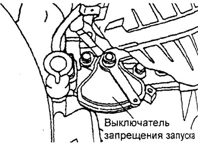
b) Check the condition of the circuit between the connector terminals at different switch positions according to the table provided.
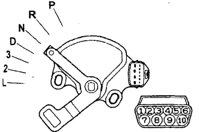
Table. Checking the switch.
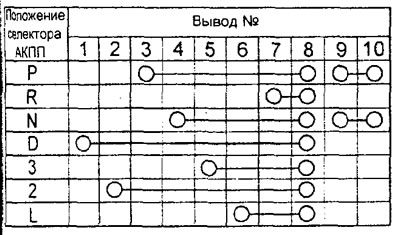
2. Check the correspondence of the gears to be engaged for each position of the automatic transmission selector and the correct operation of the gearbox in each range. Adjust if necessary.
3. Set the selector to the "N" position (neutral position).
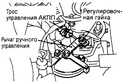
4. Loosen the adjusting nut securing the automatic transmission control cable to the manual control lever to relieve the tension of the cable.
5. Set the manual control lever to neutral position "N".
6. Loosen the start inhibit switch mounting bolts and turn the switch housing so that the hole in the housing flange aligns with the hole on the manual control lever (section A-A in the figure).
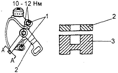
Adjusting the automatic transmission control cable and the start inhibit switch. 1 - bolts, 2 - start inhibit switch lever, 3 - start inhibit switch.
7. Tighten the start inhibit switch mounting bolts.
Note: Do not change the position of the start inhibit switch.
Tightening torque: 10 - 12 Nm
8. Slightly pull the cable connecting the automatic transmission selector to the control valve block in the direction of the arrow and then tighten the adjusting nut.
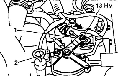
Adjusting the automatic transmission control cable and the start inhibit switch (continued). 1 - adjusting nut, 2 - start inhibit switch lever.
Tightening torque: 10 - 14 Nm
9. Make sure that the automatic transmission selector is in the "N" position (neutral position).
10. Check that the gears engaged correspond to each position of the automatic transmission selector, and make sure that the automatic transmission operates correctly in each range.
Checking the operation of the automatic transmission selector
1. Raise the parking brake lever.
2. Move the CVT selector from position to each position and check that the selector shifts smoothly and clearly.
3. Check that the engine starts when the selector is in the "P" or "N" position, and that the engine cannot be started when the selector is in other positions.
4. Start the engine, release the parking brake lever and check the operation of the gearbox control mechanism.
When moving the selector from position "N" to "D", "3", "2" or "L" the vehicle should move forward, and when moving the selector to position "R" the vehicle should move in reverse).
5. Turn off the engine.
6. Turn the ignition key to the "ON" position, move the automatic transmission selector from the "P" position to the "R" position and make sure that when the automatic transmission selector is in the "R" position, the reversing lights are on and the buzzer sounds. Note: the ignition switch and selector lock systems do not allow the CVT to be switched to unacceptable operating modes if switching can lead to a breakdown, therefore, to move the selector from the "P" position to other positions, you need to press the brake pedal and turn the key in the ignition switch to any position except "LOCK".
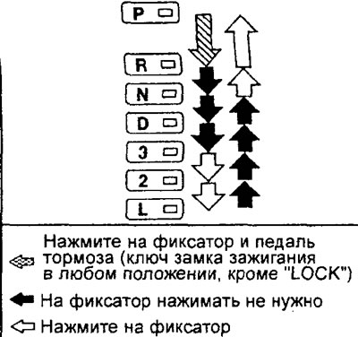
Checking and adjusting the ignition lock mechanism
1. Checking the operation of the ignition lock system.
a) Check that if, with the brake pedal depressed, the ignition key is in the "LOCK" position or removed, the selector cannot be moved from the "P" position to any other position without pressing the selector lock.
b) Check that if the ignition key is in any position except "LOCK", the selector can be moved from the "P" position to any other position with the brake pedal depressed and the lock button pressed. Check the smoothness of the selector movement.
c) Check that it is impossible to turn the ignition key to the "LOCK" position with the selector in any position except "P" (brake pedal released). Check that the ignition key can be smoothly turned to the "LOCK" position when the selector is in the "P" position (brake pedal released).
d) If the system operation differs from that specified above, adjust the ignition lock cable.
2. Adjusting the ignition lock cable.
a) Remove the lower part of the center console (see chapter "Body").
b) Set the selector to position "P" and the ignition key to the "LOCK" position.
c) Loosen the ignition lock cable fastening nut.
d) Gently pull the locking cam in the direction "A" indicated by the arrow in the figure and, holding it in this position, tighten the ignition lock cable fastening nut.
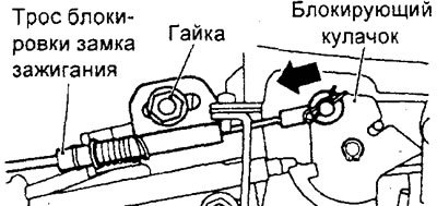
d) Install the lower part of the center console (see chapter "Body").
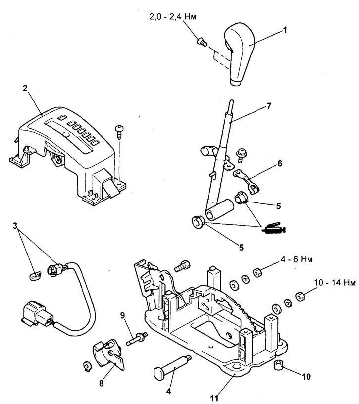
Automatic transmission selector. 1 - selector handle, 2 - selector position indicator panel, 3 - selector position indicator, 4 - bolt, 5 - bushing, 6 - locking spring, 7 - selector lever, 8 - locking cam, 9 - pin, 10 - bushing, 11 - selector bracket.
Checking and adjusting the automatic transmission selector lock system
1. Checking the operation of the selector lock system.
a) Check that if, with the brake pedal pressed, the ignition key is in the "ACC" position, the selector cannot be moved from the "P" position to any other position without pressing the selector lock.
b) Check that if, with the brake pedal pressed, the ignition key is in the "ACC" position, the selector can be moved from the "P" position to any other position by pressing the selector lock.
c) Check that if, with the brake pedal released and the lock button pressed, the ignition key is in the "ACC" position, the selector can be moved from the "R" position to the "P" position.
d) If the operation of the systems differs from that specified above, adjust the selector lock cable.
2. Adjusting the automatic transmission selector lock cable.
a) Remove the lower part of the center console (see chapter "Body").
b) Set the selector to position "P"
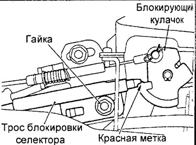
c) Loosen the selector lock cable mounting nut.
d) Adjust the position of the cable so that its edge is located in the middle of the red mark of the locking cam, as shown in the figure.
d) Tighten the cable mounting nut.
e) Install the lower part of the center console (see chapter "Body").
e) Install the lower part of the center console (see chapter "Body").
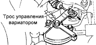
4. Pull the cable slightly in the direction "A" indicated by the arrow in the figure and, holding it in this position, tighten the automatic transmission control cable mounting nut.
Tightening torque: 12 ±2 Nm
5. Install the battery bracket and battery.