



Removal
− Before you begin removing parts, perform the following operations:
- a) (MPI engine) Remove the engine crankcase protective cover.
- b) Drain the coolant.
- c) (GDI engine) Remove the engine cover.
- d) Remove the air filter.
- d) (MPI engine) Remove the thermostat.
- e) (4G93-GDI Engine) Remove the exhaust manifold.
- g) (GDI engine) Remove the EGR valve servo.
− The parts are removed in the order of numbers shown in the figure "Removing the cooling system hoses and pipes".
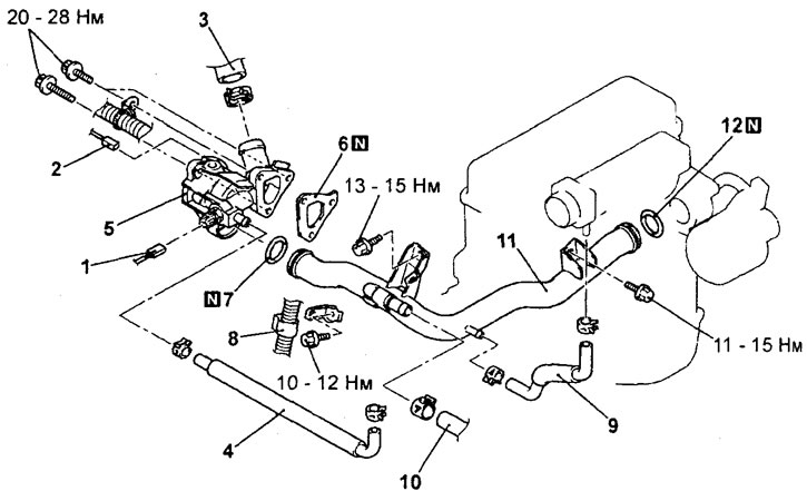
Removal the cooling system hoses and tubes (4G15-MPI engine). 1 - coolant temperature sensor connector; 2 - coolant temperature gauge sensor connector; 3 - connection of the upper radiator hose; 4 - cooling system hose; 5 - thermostat housing assembly; 6 - thermostat housing gasket; 7 - O-ring gasket; 8 - Engine management system wiring harness retainer; 9 - cooling system hose; 10 - heater hose connection; 11 - cooling system inlet pipe; 12 - O-ring gasket.
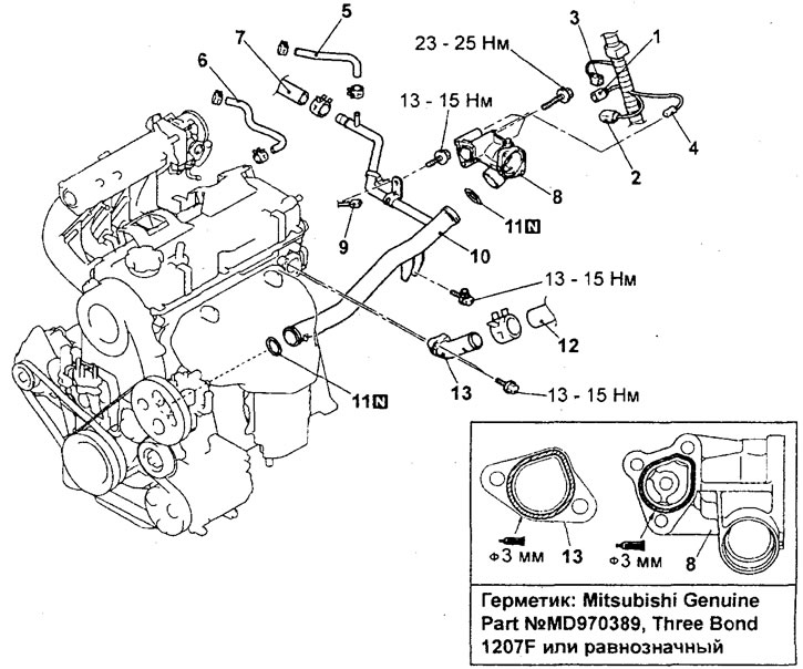
Removal the cooling system hoses and tubes (4G93-MPI engine). 1 - coolant temperature sensor connector; 2 - knock sensor connector; 3 - camshaft position sensor connector; 4 - coolant temperature gauge sensor connector; 5 - cooling system hose; 6 - cooling system hose; 7 - heater hose connection; 8 - thermostat housing assembly; 9 - knock sensor connector connection; 10 - cooling system inlet pipe; 11 - O-ring gasket; 12 - connection of the upper radiator hose; 13 - outlet pipe of the cooling system.
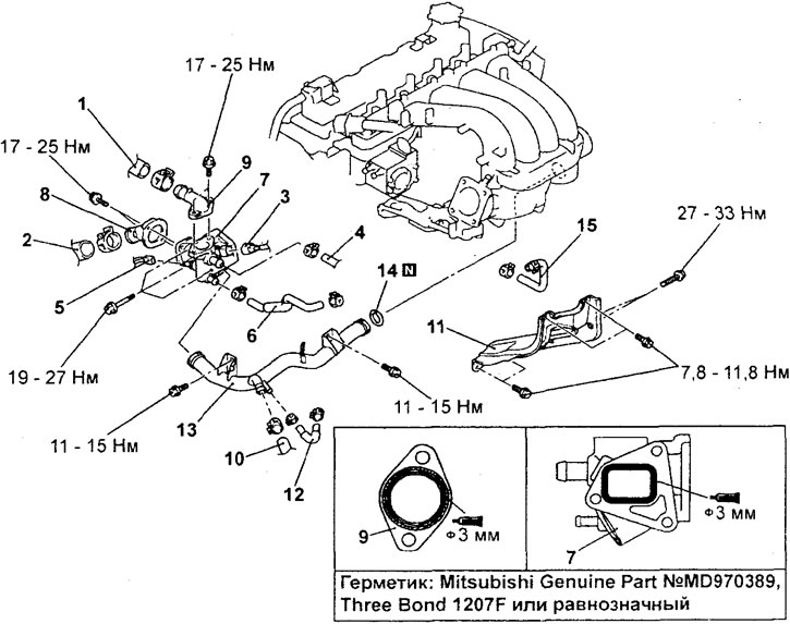
Removal the cooling system hoses and pipes (4G15-GDI engine). 1 - connection of the upper radiator hose; 2 - connection of the lower radiator hose; 3 - coolant temperature sensor connector; 4 - heater hose connection; 5 - coolant temperature gauge sensor connector; 6 - cooling system hose; 7 - thermostat housing assembly; 8 - cooling system inlet pipe; 9 - Cooling system outlet pipe; 10 - heater hose connection; 11 - intake manifold stand; 12 - Cooling system hose; 13 - cooling system inlet pipe; 14 - O-ring; 15 - cooling system hose.
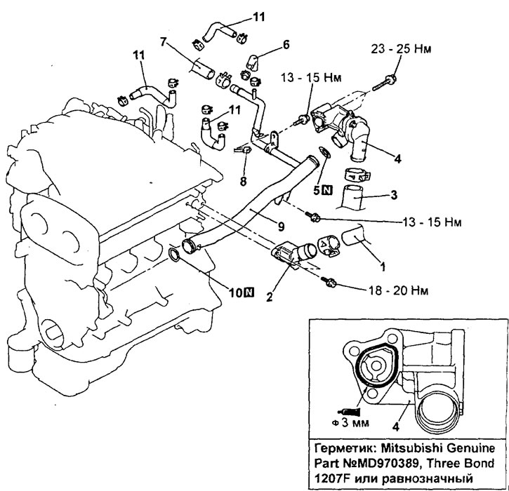
Removal the cooling system hoses and pipes (4G93-GDI engine). 1 - connection of the upper radiator hose; 2 - cooling system inlet pipe; 3 - connection of the lower radiator hose; 4 - thermostat housing assembly and cooling system outlet pipe; 5 - O-ring gasket; 6 - cooling system hose; 7 - heater hose connection; 8 - knock sensor connector; 9 - cooling system inlet pipe; 10 - O-ring gasket; 11 - cooling system hose.
- When removing parts, pay attention to the following operations:
1. Removing the upper and lower radiator hoses.
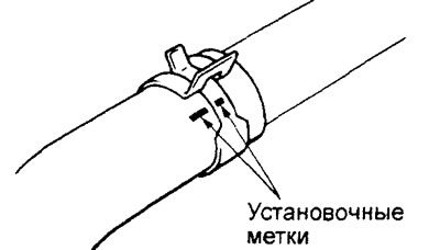
Before disconnecting the upper and lower radiator hoses, place relative position alignment marks on the hose and hose clamp.
Caution: After disconnecting the hoses from the radiator, it is necessary to plug the holes in the hose and radiator to prevent dust or foreign particles from getting into them.
2. (4G15-GDI engine) Removing the cooling system supply pipe.
a) Loosen the intake manifold resonator mounting bolts.
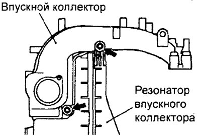
b) Move the intake manifold resonator and remove the cooling system supply pipe.
Examination
1. Before installation, check the hoses and tubes for cracks, damage and blockages. Replace them if necessary.
2. The procedure for checking the coolant temperature sensor is given in the chapter "Fuel injection system".
3. The procedure for checking the coolant temperature gauge sensor is given in the chapter "Body electrical equipment".
Installation
− Installation of parts is carried out in the reverse order of removal.
- When installing parts, pay attention to the following operations:
1. Installing the O-ring gasket of the cooling system inlet pipe.
Put the O-ring on the water inlet pipe and apply some coolant or water to its outer surface, then install the pipe. Applying coolant or water will make the installation of the water inlet pipe easier.
Attention:
- Do not allow engine oil or grease to come into contact with the O-ring surface.
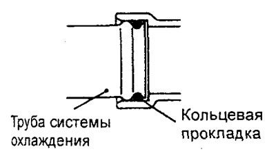
- Do not allow sand, dust, etc. to enter the connection points of the cooling system inlet pipe.
2. Installing the thermostat housing assembly, the outlet pipe of the cooling system (engine 4G15-GDI and 4G93-MPI).
a) Using a scraper or a metal brush, completely clean the adhered surfaces from the remains of the old sealant. After cleaning, degrease the surfaces for applying the sealant.
b) Apply sealant evenly in a continuous bead approximately 3 mm in diameter to the mating surface of the thermostat housing to the cylinder head, the outlet pipe of the cooling system (4G15-GDI and 4G93-MPI engines).
Mitsubishi Genuine Parts Sealant No. MD970389, Three Bond 1207F i or equivalent
Caution: Do not apply more sealant than necessary.
c) Install the thermostat housing assembly, the coolant outlet pipe (4G15-GDI and 4G93-MPI engine) before the sealant dries (within 15 minutes after applying the sealant). Do not apply the sealant to areas other than those specified above.
3. Connecting the upper and lower radiator hoses.
a) When connecting the radiator hoses, push the hose onto the pipe until it stops against the protrusion of the pipe, then tighten the clamp.
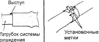
b) The hose clamp should always be installed in the position where the clamp was previously installed. Therefore, before installing the clamp, align the installation marks on the hose clamp and the hose, then connect the hose.
− After completing the installation of the parts, perform the following operations.
- a) (GDI engine) Install the EGR valve servo.
- b) (4G93-GDI Engine) Install the exhaust manifold.
- c) (MPI engine) Install thermostat.
- d) Install the air filter.
- d) (GDI engine) Install the engine cover.
- e) Fill with coolant,
- g) (MPI engine) Install the engine crankcase guard.