



Removal
− Before you begin removing parts, perform the following operations:
- a) Drain the coolant.
- b) Remove the engine crankcase protective cover.
- c) Drain the CVT or automatic transmission working fluid.
- d) Remove the air intake duct
- d) Remove the battery and battery tray.
− The parts are removed in the order of numbers shown in the figure "Removing the radiator and electric fan".
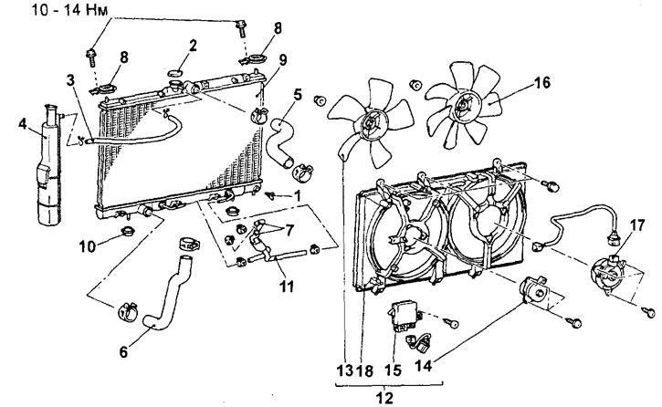
Removal the radiator and electric fan (engine 4G93-MPI). 1 - drain plug, 2 - radiator cap, 3 - expansion tank hose, 4 - expansion tank, 5 - upper radiator hose, 6 - lower radiator hose, 7 - automatic transmission fluid cooler hose connection, 8 - upper radiator support, 9 - radiator, 10 - lower radiator support, 11 - automatic transmission fluid cooler hoses assembled, 12 - diffuser and electric fans of the radiator and air conditioner condenser assembled, 13 - radiator fan, 14 - radiator fan electric motor, 15 - electric fans controller, 16 - air conditioner condenser fan, 17 - air conditioner condenser fan electric motor, 18 - fan diffuser.
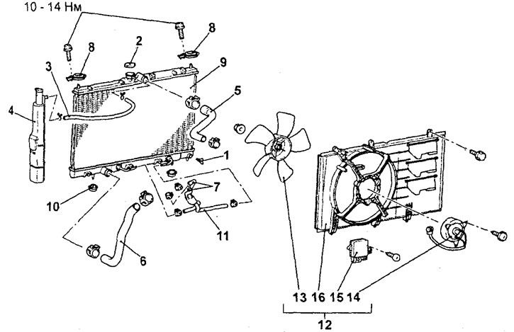
Removal the radiator and electric fan (except for the 4G93-MPI engine). 1-drain plug, 2-radiator cap, 3-expansion tank hose, 4-expansion tank, 5-upper radiator hose, 6-lower radiator hose, 7-connection of the CVT working fluid cooler hose, 8-upper radiator support, 9-radiator, 10-lower radiator support, 11-assembled CVT working fluid cooler hoses, 12-diffuser and electric fan of the radiator and air conditioner condenser, 13-radiator and air conditioner condenser fan, 14-electric motor of the radiator and air conditioner condenser fan, 15-electric fan controller, 16-fan diffuser.
- When removing parts, pay attention to the following operations:
1. Removing the upper and lower radiator hoses.
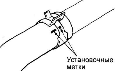
Before disconnecting the upper and lower radiator hoses, place relative position marks on the hose and hose clamp.
Caution: After disconnecting the hoses from the radiator, it is necessary to plug the holes in the hose and radiator to prevent dust or foreign particles from getting into them.
2. Removing the CVT or automatic transmission fluid cooler hose.
After disconnecting the hose from the radiator, plug the holes in the hose and radiator to prevent dust or foreign particles from getting in.
Examination
1. Checking the radiator.
a) Check for foreign particles (dirt, leaves, fluff, etc.) between the radiator fins. Clean with compressed air if necessary.
b) Check the radiator fins for bending or damage.
c) Check the radiator for damage and any scale, rust or corrosion deposits.
d) Check the radiator hoses for cracks, damage or wear.
d) Check the expansion tank for damage.
e) Check the radiator cap spring for wear or damage.
g) Check the radiator cap gasket for damage or cracks.
2. Checking the fan.
a) Check the fan blades for damage or cracks.
b) Check for cracks or damage around the bolt holes in the fan hub.
c) If any part of the fan is damaged, replace the fan assembly.
3. (Except for 4G93-MPI engine) Checking the electric fan controller.
a) Disconnect the radiator fan motor and air conditioner condenser connector.
b) Start the engine and let it idle.
c) Turn on the air conditioner and leave the engine running to warm up the coolant to a temperature of approximately 80°C or more.
d) Measure the voltage between the terminals of the electric fan controller connector and make sure that the voltage value changes in accordance with the specified points (I) - (III).
(I) 0B
(II) 8.2 ±2.6 V
(III) Battery voltage (on-board network) + 2.6 V
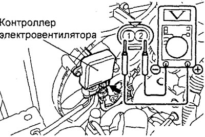
d) If the voltage value does not change according to the above points, replace the electric fan controller.
4. (Engine 4G93-MPI) Checking the electric fan controller.
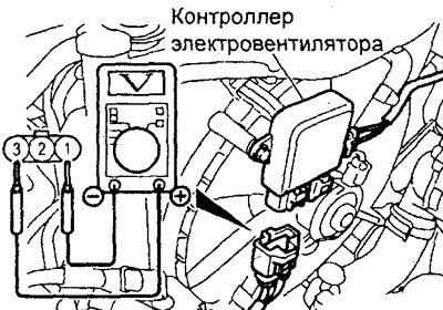
a) Disconnect the electric fan controller connector.
b) Turn on the ignition (ignition key in the "ON" position) and measure the voltage between the terminals of the connector disconnected from the controller.
Nominal value - battery voltage
c) Connect the fan controller connector and disconnect the air conditioner condenser fan motor connector.
d) Make sure the air conditioner is turned off (switch in the "OFF" position), then start the engine and let it idle.
d) Measure the voltage between the terminals of the electric fan controller connector from which the connector was disconnected in subparagraph "c".
Nominal value is 1V and below
e) Turn on the air conditioner (switch in the "ON" position).
g) Check that the radiator electric fan rotates, then measure the voltage between the terminals of the electric fan controller connector and check that the voltage value changes according to the specified points (I) - (II).
(I) 8.2 ±2.6 V
(II) Battery voltage (on-board network) + 2.6 V
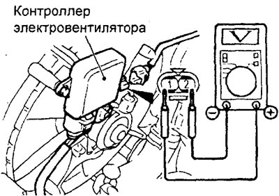
h) If the voltage value does not change according to the above points, replace the fan controller.
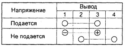
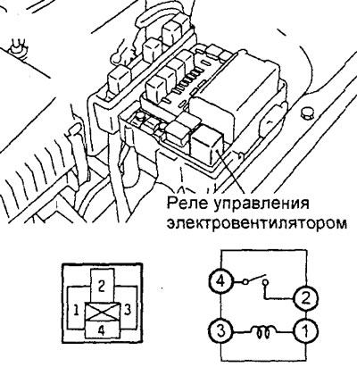
5. Checking the electric fan control relay (except for the 4G93-MPI engine) or the electric fan control relay (4G93-MPI engine).
a) Remove the electric fan control relay from the relay box in the engine compartment.
b) Check the condition of the circuit between the connector terminals according to the table provided.
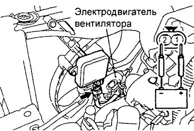
6. Checking the radiator fan motor and air conditioner condenser.
a) To check the operation of the fan motor, connect the wires of the battery terminals to the terminals of the fan motor connector as shown in the figure.
b) Check that there is no extraneous noise when the fan rotates.
Troubleshooting models with electric fan controller
1. If the radiator fan and condenser fan do not work, the power line or ground of the electric fan controller is probably broken, or the electronic engine control unit is faulty. One of the following faults may be present:
- a) The fuse link has burned out.
- b) The electric fan control relay is faulty.
- c) The electric fan controller is faulty.
- d) Malfunction of the electronic engine control unit.
- d) A break in the wiring harness or poor contact in the connector.
2. If the speed does not change or the electric fan of the radiator and air conditioner condenser does not turn off, then the electric fan controller, based on the signals from the electronic engine control unit, probably gives an incorrect mode (rotation speed) of the fan motor. One of the following malfunctions may be present:
- a) The electric fan control relay is faulty.
- b) The electric fan controller is faulty.
- c) Malfunction of the electronic engine control unit.
- d) A break in the wiring harness or poor contact in the connector.
3. If the electric fan does not work, then the fan motor is probably faulty, the electric fan controller is faulty, or there is an open circuit between the controller and the fan motor.
Installation
− Installation of parts is carried out in the reverse order of removal.
- When installing the parts, pay attention to the operation of installing the lower and upper radiator hoses.
a) When connecting the radiator hoses, push the hose onto the pipe until it stops against the protrusion of the pipe, then tighten the clamp.
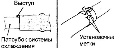
b) The hose clamp should always be installed in the position in which the clamp was previously installed. Therefore, before installing the clamp, align the installation marks on the hose clamp and the hose, then connect the hose.
− After completing the installation of the parts, perform the following operations.
a) Install the battery tray and battery.
b) Install the air intake duct
c) Fill the CVT or automatic transmission with working fluid.
d) Install the engine crankcase protective cover.
d) Fill with coolant and check for leaks.