



Removal
Note: The oil pan removal and installation procedures that need to be taken into account are given in the section "Oil pan".
− The parts are removed in the order of numbers shown in the figure "Removing the oil pump housing".
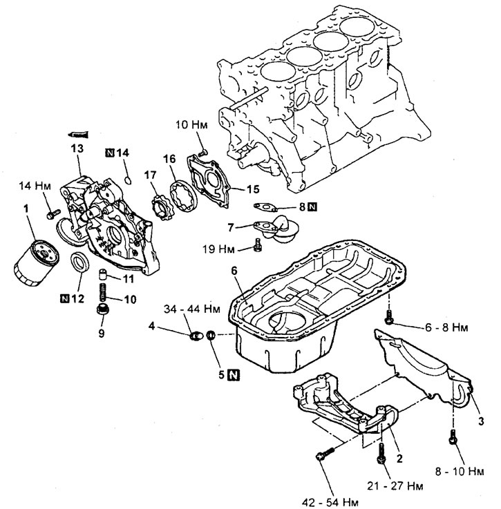
Removal the oil pump housing (engine 4G15). 1 - oil filter, 2 - gearbox mounting bracket, 3 - gearbox housing protective cover, 4 - drain plug, 5 - drain plug gasket, 6 - oil pan, 7 - oil receiver, 8 - oil receiver gasket, 9 - plug, 10 - pressure relief valve spring, 11 - pressure relief valve plunger, 12 - front crankshaft oil seal, 13 - oil pump housing, 14 - O-ring gasket, 15 - oil pump cover, 16 - oil pump driven rotor, 17 - oil pump driving rotor.
- When removing parts, pay attention to the operation of removing the leading and driven rotors of the oil pump.
a) Loosen the bolts and remove the oil pump cover.
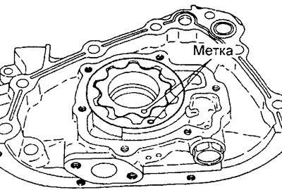
b) Before removing the oil pump, apply alignment marks to the leading and driven rotors of the pump. This is necessary to ensure correct subsequent assembly.
Examination
Checking the oil pan and oil receiver
The verification procedures are provided in the section "Oil pan".
Checking the oil filter seat
1. Check that there is no damage to the contact surface of the oil filter.
2. Check for cracks or oil leaks.
Checking the oil pump
1. Check the rotor teeth for wear and damage.
2. Install the driving and driven rotors into the oil pump housing and check that they rotate smoothly without jamming.
3. Checking the clearances of the oil pump rotors.
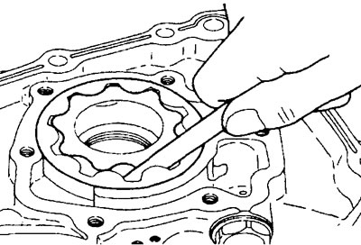
a) Check the clearance at the tops of the pump rotor teeth.
The gap at the tops of the rotor teeth (nominal) is 0.06 - 0.18 mm
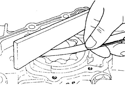
b) Check the end clearance of the leading and driven rotors of the pump.
End clearance:
- nominal - 0.04 - 0.10 mm
- maximum permissible - 0.20 mm
c) Check the clearance between the outer surface of the driven rotor and the oil pump housing.
Clearance between rotor and housing:
- nominal - 0.10 - 0.18 mm
- maximum permissible - 0.35 mm
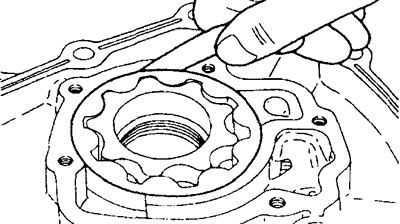
d) If either gap is greater than the maximum, replace both rotors. Replace the oil pump assembly if necessary.
Checking the pressure reducing valve
1. Check the ease of movement of the plunger of the pressure reducing valve in the oil pump housing.
2. Check the condition of the pressure reducing valve spring (no breakage, shrinkage).
Installation
− Installation of parts is carried out in the reverse order of removal.
- When installing the parts, pay attention to the following operations.
Caution: Apply engine oil to all moving parts during assembly.
1. Installation of the leading and driven rotors of the oil pump.
a) Align the timing marks and install the driven and driving rotors into the oil pump housing.
b) Apply engine oil to the surfaces of the pump rotors.
c) Install the oil pump cover and tighten the mounting bolts.
2. Installing the oil pump housing
a) Remove any remaining old sealant from the surface of the cylinder block (pump housing installation site) and the oil pump housing.
b) Apply the specified sealant in a continuous bead 3 mm in diameter to the oil pump body in the places shown in the figure.
Sealant MITSUBISHI GENUINE Part # MD970389, Three Bond No.1207F or equivalent
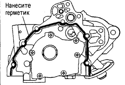
Engine 4G15 (view from the cylinder block).
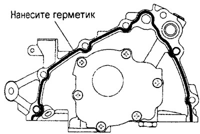
Engine 4G93 (view from the cylinder block).
c) Fix the oil pump housing to the cylinder block within 15 minutes after applying the sealant.
Caution: Do not mix up the mounting bolts when installing the oil pump housing, as they differ in length.
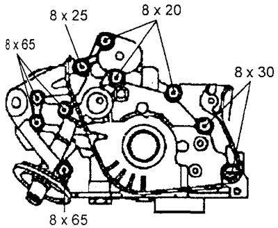
Engine 4G15 (view from the timing belt side).
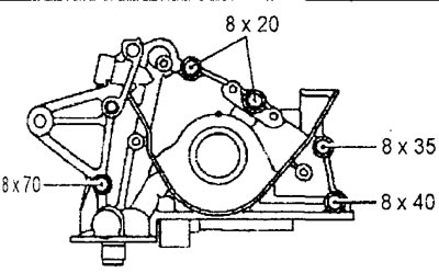
Engine 4G93 (view from the timing belt side).
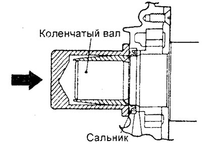
4. Installing the front crankshaft oil seal.
a) Install the guide sleeve onto the front of the crankshaft and apply engine oil to the outer surface of the guide sleeve.
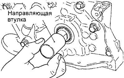
Engine 4G15.
b) Apply engine oil to the seal lip and insert the seal along the guide sleeve until it contacts the oil pump housing.
c) Lightly tap the mandrel to install the seal flush with the oil pump housing.
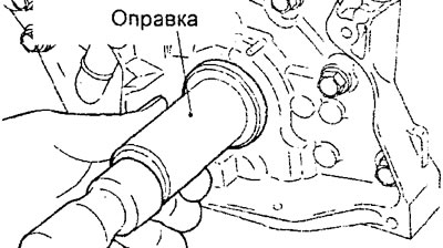
Engine 4G15.
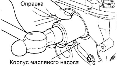
Engine 4G93.
5. Installing the oil pan.
The installation procedure is given in the section "Oil pan".
6. Installation of the drain plug and oil filter is given in the relevant section of the chapter "Maintenance and general check and adjustment procedures".