



Contents: Technical operations on the car ⤓ Convergence ⤓ Control rod: front view ⤓ Checking the axial play of the…⤓ Checking the axial play of the upper…⤓ Checking the axial play of the ball…⤓ Checking the condition of the…⤓
The car uses a rear multi-link independent suspension with longitudinal levers. The shock absorber is hydraulic, cylindrical, gas-filled, double-acting.
Technical characteristics (coil spring)
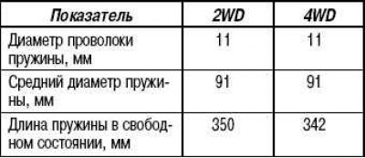
Basic data for adjustment and control
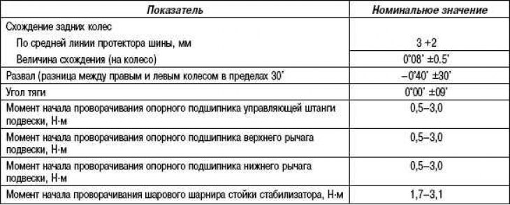
* The difference between the right and left wheels should not be more than 30'.
Lubricants

Technical operations on the car
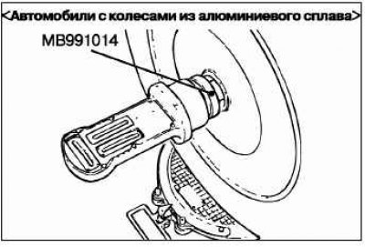
Caution! If the wheel hub shaft nuts (self-locking nuts) are loose or the wheel alignment tool (MB991014) is not properly secured, it is not permitted to check the wheel hub bearings.
Caution! For vehicles with aluminum alloy wheels: Attach the wheel alignment gauge to the wheel drive shaft using the special tool (MB991014). Tighten the special tool with the same tightening torque of 175 ±25 N and the rear wheel hub nut (self-locking nut). If the camber is not within the standard value, perform the following operations.
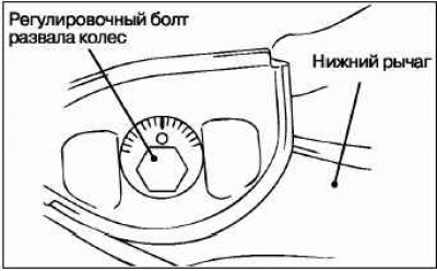
Disconnect the control rod from the trailing arm.
Adjust the camber by turning the adjusting bolt (lower control arm mounting bolt located on the inside of the body).
- LH: Clockwise from the front of the car (+) camber.
- RH: Clockwise from the front of the vehicle (–) camber.
- The scale has a division value of approximately 14'.
To prevent the bushings from being destroyed, the connecting bolt is first pre-tightened, then finally tightened to a torque of 90+10 Nm, with the unloaded vehicle on the ground.
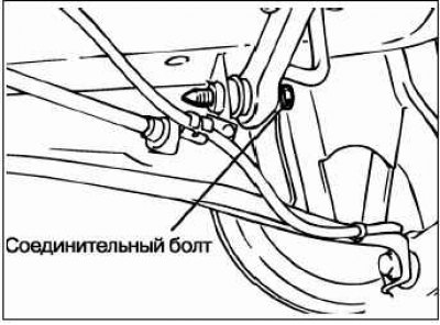
Secure the control rod to the trailing arm.
After adjusting the camber, adjust the toe-in of the car's wheels.
Convergence
Nominal value: at the center line of the tire tread, 3 +2 mm.
Toe-in (per wheel): 0°08±0.5'.
If the toe-in is not within the specified value, adjust it as follows.
Attention! To prevent destruction of the bushings, the control rod mounting nut is first pre-tightened, then finally tightened to a torque of 120+10 Nm, and the unloaded vehicle must be on the ground.
Control rod: front view
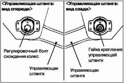
Adjust the toe-in by turning the adjusting bolt (the suspension control rod mounting bolt located on the inside of the body).
- LH: Clockwise from the front of the vehicle (+) toe-in.
- RH: Clockwise from the front of the vehicle (–) toe-in.
- Turning the adjusting bolt by one division on the scale changes the toe-in by 2.6 mm (one-sided toe-in angle corresponds to 16').
Checking the axial play of the control rod support bearing
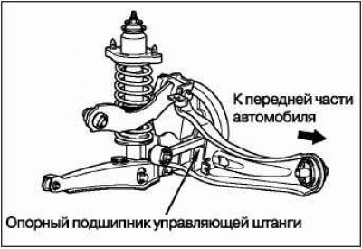
Raise the car.
By shaking the control rod up and down by hand, check for axial play in the support bearing. If there is significant play, replace the control rod.
Checking the axial play of the upper suspension arm support bearing
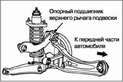
Raise the car.
By shaking the upper control arm up and down by hand, check for axial play in the support bearing. If there is significant play, replace the upper control arm.
Checking the axial play of the ball joint of the lower suspension arm
Raise the car.
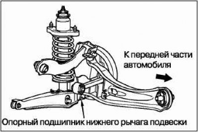
Disconnect the stabilizer bar and shock absorber from the lower control arm.
By shaking the lower control arm up and down by hand, check for axial play in the support bearing. If there is significant play, replace the support bearing of the lower control arm.
Once the check is complete, reconnect the stabilizer bar and shock absorber to the lower suspension arm.
Checking the condition of the protective cover of the stabilizer strut ball joint
Check the condition of the stabilizer strut ball joint protective boots for cracks and damage by squeezing the boots with your fingers.
If there are cracks or damage to the protective cover, replace the stabilizer bar assembly.
Caution: Cracks or damage in the protective boot may cause destruction of the ball joint.