



Contents: Removal ⤓ Installation ⤓
Removal
- Before removing the instrument panel, read the safety precautions for servicing the SRS additional safety system components. Set the front wheels to move straight ahead and turn off the ignition. Otherwise, the spiral wire may be damaged and the SRS additional safety system may be disabled. As a result, the airbag may deploy unauthorized, which may result in injury.
- Removal and installation the instrument panel are operations that must be performed with care. When removing, make sure that the electrical connectors are completely disconnected. When reinstalling, make sure that the wiring harnesses are correctly routed and secured.
Notes.
- To prevent damage to parts, wrap the screwdriver blade in a cloth.
- To avoid injuring your hands, wear gloves.
- Remove the center floor console.
- Remove the self-tapping screws and remove the lower instrument panel cover (Fig. 17.87).
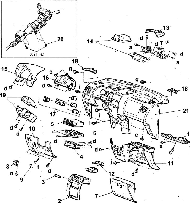
Fig. 17.87. Instrument panel: 1 - lower cover of the instrument panel; 2 - lower central panel; 3 - Hazard warning light switch; 4 - box for small items; 5 - radio receiver; 6 - Heating and air conditioning control unit; 7 - glove box; 8 - hood release handle; 9 - bottom plug; 10 - lower trim of the instrument panel on the driver's side; 11 - lower trim of the instrument panel on the passenger side; 12 - ashtray; 13 - Multifunctional display trim; 14 - Multifunctional display; 15 - Instrument cluster trim; 16 - instrument cluster; 17 - Instrument panel switches; 18 - side ventilation grille; 19 - steering column covers; 20 - steering column mounting bolts; 21 - Instrument panel: a - Self-tapping screw, 5x10; b - self-tapping screw, 5x16; c-tapping screw, 4.8x13; d - self-tapping screw (black), 4.8x16; e - screw with washer, 6x12; f- screw washer, 6x16; g - self-tapping bolt, 6x16; h - flange bolt, 5x16; i - flange bolt, 6x14.29; j - flange bolt, 6x16; k - bolt with flange, 6x20
- Remove the lower center panel and disconnect the connector from the hazard warning light switch.
- Remove the small items box.
- Remove the radio.
- Remove the screws and pull the heating and air conditioning control unit out of the instrument panel, then disconnect the electrical connectors from the unit.
- Remove the glove box.
- Remove the screws, disconnect the cable and remove the hood release handle.
- Remove the plugs, unscrew the screws and remove the lower instrument panel trim on the driver's side and passenger's side.
- Remove the ashtray.
- Remove the multifunction display cover.
- Remove the screws, disconnect the connectors and remove the multifunction display.
- Remove the screws and remove the instrument cluster trim.
- Remove the screws, disconnect the connectors and remove the instrument cluster.
- Use a screwdriver to lever out the instrument panel switches and disconnect the electrical connectors from them.
- Remove the side ventilation grilles.
- Remove the front pillar trim.
- Remove three screws, release three latches and remove steering column covers.
- Remove the steering wheel and driver's airbag.
- Remove the steering column mounting bolts and lower the steering column down.
- Make sure all electrical connectors are disconnected from the instrument panel.
- Remove the mounting screws in the central and side parts and remove the instrument panel assembly.
Installation
- The instrument panel is installed in the reverse order of removal.
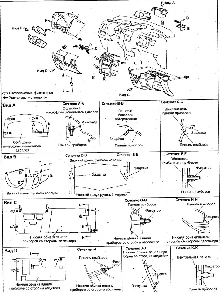
Fig. 17.88. Location of instrument panel latches and fasteners
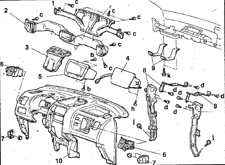
Fig. 17.89. Instrument panel elements: 1 - air duct for glass heater; 2 - distribution air duct; 3 - central ventilation duct; 4 - front passenger airbag; 5 - glove box; 6 - side ventilation grille; 7- lower bracket of the instrument panel; 8 - middle support of the instrument panel; 9 - shock absorbing element; 10 - instrument panel; b - self-tapping screw, 5x16; c - self-tapping screw, 4.8x13; d - self-tapping screw (black), 4.8x16; h - flange bolt, 5x16; j - flange bolt, 6x16; k - bolt with flange, 6x20