



1988 Precis (with Bosch generator)
1. Remove the generator.
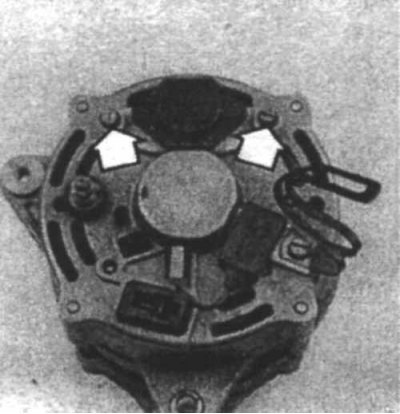
17.2 To remove the voltage regulator/brush holder, unscrew the two mounting screws (indicated by arrows) and remove the brush holder
2. Loosen the voltage regulator mounting screws (17.2).
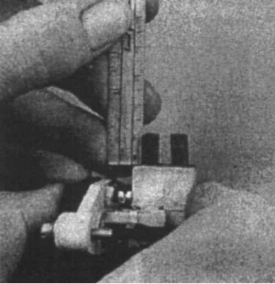
17.3 Measure the length of the brushes using a small ruler - if they are shorter than 2-3 mm, replace them
3. Remove the brush holder and measure the length of the brushes. If they are shorter than 4.6 mm, replace them.(17.3)
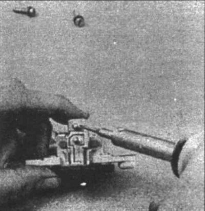
17.4 To remove worn brushes from the holder, carefully unsolder the brush wires
4. Unsolder the brush wires (17.4) and remove the brushes and springs.
5. Installation is carried out in the reverse order of removal. Solder the new brushes securely.
All other models (with Melco generator)
6. Remove the generator.
7. Unscrew the bolts securing the generator halves.
8. Clamp the front of the generator in a vice.
9. Unscrew all nuts from the back of the generator.
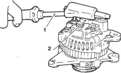
17.10a To facilitate disassembly of the generator, heat the bearing housing
1. Soldering iron; 2. Bearing housing
10. Heat the rear box with a powerful soldering iron (17.10a
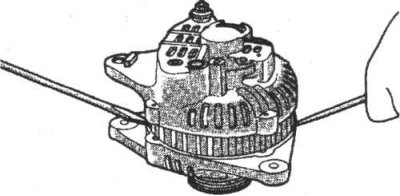
17.10b Using two screwdrivers, separate the halves of the generator and using two screwdrivers, pry off the rear casing
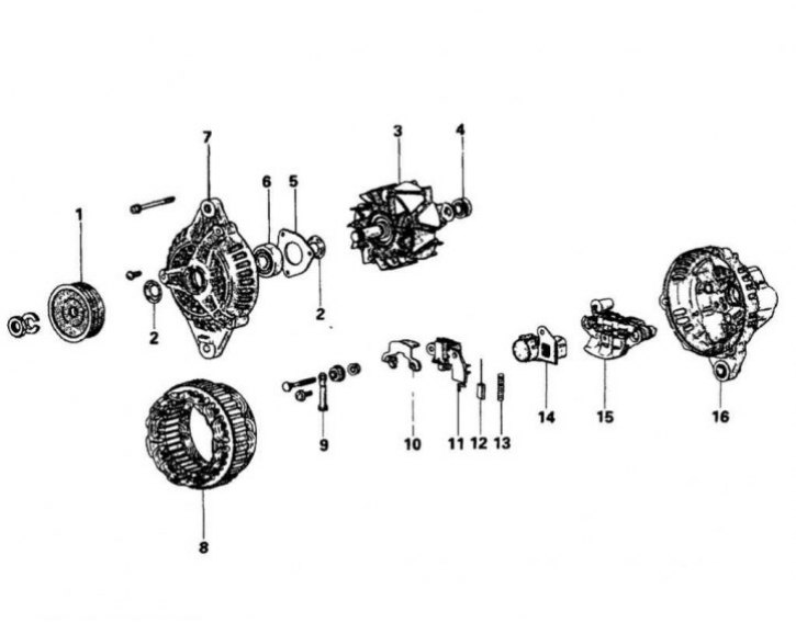
17.11 Melco Generator Elements
1. Generator pulley; 2. Seal; 3. Rotor; 4. Rear bearing; 5. Bearing fastening; 6. Front bearing; 7. Front bracket; 8. Stator; 9. Terminal; 10. Plate; 11. Regulator and brush holder; 12. Brush; 13. Brush spring; 14. Bushing; 15. Restorer; 16. Rear bracket; 11. Unsolder the brush holder/regulator (17.11)
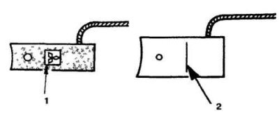
17.12a If the brushes are worn beyond the limit line, they must be replaced
1. Boundary line; 2. Boundary line
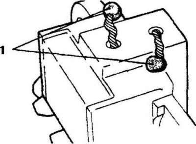
17.12b When replacing brushes, solder the wires at the following points
1. Solder
12. Inspect the brushes and replace them if necessary (17.12a and 17.12b).
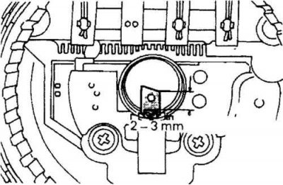
17.13 When installing new brushes, they must protrude from the holder by a certain amount
13. When installing new brushes, solder the ends of the brush wires so that the brushes protrude from the holder by 1.9-2.9 mm (17.13).
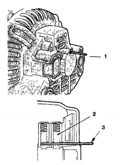
17.14 When joining the two halves together, thread a wire through the rear casing and brush holder to secure the brushes in the holder
1. Wire; 2. Brush; 3. Wire
14. Assembly is carried out in the reverse order of disassembly (17.14).