
English Русский
Български
Беларускі
Український
Српски
Hrvatski
Română
Polski
Slovenský
Magyar
Articles Bookmark Contacts Sitemap   
Company Audi Company Ford Company Hyundai Company Kia Company Mazda Company Mercedes-Benz Company Nissan
MitsubishiMan.ru


Home Colt Lancer Galant L200 Outlander Pajero Others
Galant 6 and 7 (1987-1998) Galant 5 (1983-1989, petrol)

Voltage Regulator/Generator Brushes — Replacement (Mitsubishi Galant 5)

  • Home
  • Galant
  • 5 (1983-1989, petrol)
  • Power unit
  • Engine electrical equipment
  • Voltage Regulator/Generator Brushes — Replacement
0
Contents: Precis 1988 (Bosch type) ⤓ The rest (like Melco) ⤓

Precis 1988 (Bosch type)


Note: If you decide to replace the brushes (but not the entire regulator), you will need to desolder the old brushes from the regulator and solder the new ones in their place. If you do not have the soldering skills, leave this job to a qualified person. If you overheat and damage the regulator while performing the brush replacement procedure, you will have to buy a new one.


1. Remove the generator.

2. Unscrew the screws securing the voltage regulator (see illustration).
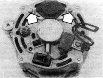


17.2 To remove the voltage regulator/brush holder assembly, unscrew the two mounting screws (shown by arrows), then remove the assembly


3. Remove the brush holder and regulator assembly and measure the brush protrusion length (see illustration). If the brush length is less than 5 mm, replace them with new ones.
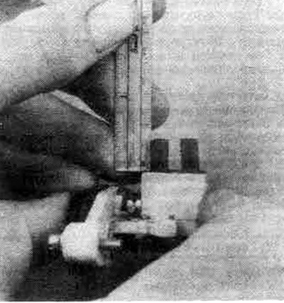


17.3. Measure the length of the brushes with a ruler; if the length is less than 5 mm, replace the brushes


Note: If you are replacing the voltage regulator, skip the next step as the new regulator has new brushes.


4. Unsolder the wire connections on the brushes, remove the brushes with springs.

5. Install in reverse order. Make sure that you solder the wires of the new brushes correctly.

The rest (like Melco)


6. Remove the generator (see section 16).

7. Unscrew the bolts that connect the two parts of the generator together.

8. Wrap the front of the generator housing with a rag and secure the front of the generator in a vice.

9. Unscrew all nuts from the rear of the generator.

10. Using a 200W soldering iron, heat the rear bearing seat in the rear housing (see illustration). Carefully insert two regular screwdrivers between the two halves of the generator (not too deep or you will damage the stator) and separate the rear housing of the generator (see illustration).
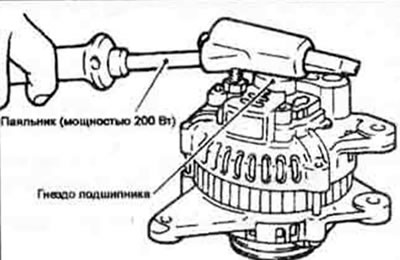


17.10a. Heating the generator rear bearing seat will facilitate separation of the generator housings
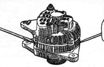


17.10b. Using two screwdrivers, separate the generator housings


Warning: Perform the operation carefully, otherwise the aluminum body may be damaged.


11. Unsolder the brush and regulator holder.
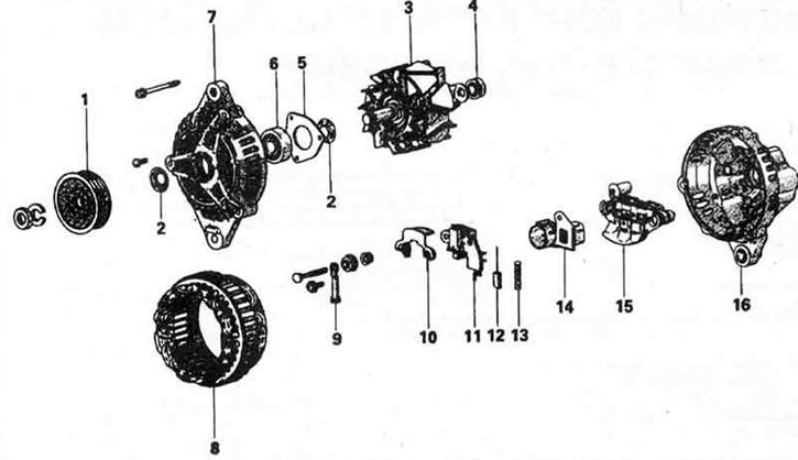


17.11. Exploded view of a Metco type generator. 1. Alternator Pulley, 2. Seal, 3. Rotor, 4. Rear Bearing, 5. Bearing Holder, 6. Front Bearing, 7. Front Bracket, 8. Stator, 9. Terminal, 10. Plate, 11. Adjuster and Brush Holder, 12. Brush, 13. Brush Spring, 14. Oil Deflector (if fitted), 15. Rectifier, 16. Rear Bracket.


Note: When heating electrical parts, it is recommended to use tweezers as a heat sink. Do not heat for more than five seconds.


12. Inspect the brushes for signs of intense wear; if necessary, replace the brushes by unsoldering them (see illustration).
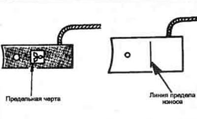


17.12a. If the brushes are worn to the limit, they must be replaced
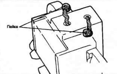


17.12b. When replacing brushes, unsolder and solder the wires in the indicated places


13. When installing new brushes, solder the wires so that the limit line on the brush protrudes from the end of the holder by approximately 2-3 mm.
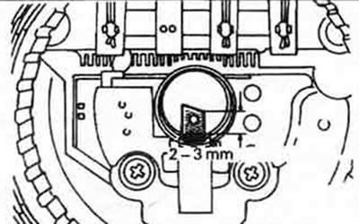


17.13. When installing new brushes, they must protrude from the holders by a certain amount


14. Install the brushes into the holder and secure them with pieces of wire so that the clips can be removed from the rear of the generator after assembly is complete (see illustration).
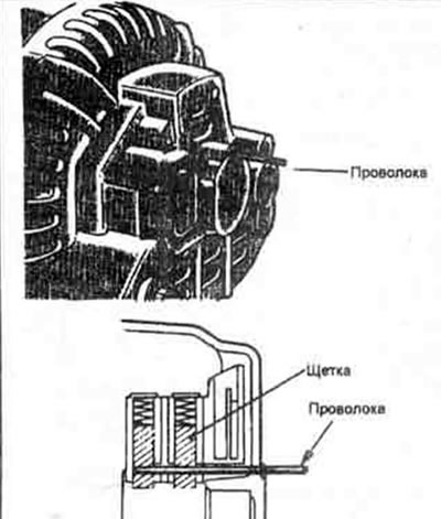


17.14 When joining the two parts of the generator housing, insert pieces of wire through the rear housing to secure the brushes in the holders


15. The rest of the assembly is carried out in reverse order.
This article is available at: russian, bulgarian, belarusian, ukrainian, serbian, croatian, romanian, polish, slovak, hungarian
This article was reviewed by: Vladimir Glazunov
Share with friends:
◀ Previous
Galant 5: Engine electrical equipment
Next ▶

Generator — removal and installation
Charging system — check
Battery Charging System — General Description and Safety Precautions
Distributor Sensor Air Gap — Checking and Adjusting
Centrifugal ignition timing regulator — checking and replacing components
Launch system — general description and safety precautions
Starter — Checking in a Car
Starter — removal and installation
Starter Solenoid Relay — Removal and Installation
Similar materials for other Mitsubishi models

➤ Voltage Regulator / Generator Brushes — Replacement Mitsubishi Colt 2 and 3 (1983-1993)
➤ Checking the generator voltage Mitsubishi Lancer 3 and 5 (1984-1992)
➤ Checking and adjusting the rear brake force regulator… Mitsubishi L200 4 (2005-2014, diesel)
➤ Checking the voltage drop on the generator wire with the… Mitsubishi Outlander 1 (2003-2008)
➤ Generator repair — checking brushes Mitsubishi Pajero 4 (2006-2021)
➤ Checking the generator output voltage drop Mitsubishi Carisma (1995-2004)
Link in different formats to this article
Comments and feedback from visitors
No comments yet


Add up two numbers 31 + 24


Galant 6 and 7 (1987-1998) 
  • General information
  • Introduction to guide
  • User manual
  • Driving and operation
  • Maintenance
  • Power unit
  • Dismantling the engine
  • Engine overhaul
  • Cooling and heating
  • Power and exhaust systems
  • Engine electrical equipment
  • Engine management systems
  • Transmission
  • Mechanical gearbox
  • Automatic gearbox
  • Clutch
  • Drive shafts and transfer case
  • Chassis and running gear
  • Brake system
  • Car suspension
  • Steering
  • Body and interior
  • Exterior (external elements)
  • Interior (internal elements)
  • Doors, locks and windows
  • Electrical equipment
  • Equipment and devices
  • Wiring diagrams Galant
  • Wiring diagrams Mirage
  • Wiring diagrams Diamante
Galant 5 (1983-1989, petrol) 
  • General information
  • Troubleshooting
  • Maintenance
  • Power unit
  • Engine repair
  • Engine overhaul
  • Cooling and heating
  • Fuel and exhaust system
  • Engine electrical equipment
  • Reducing exhaust toxicity
  • Transmission
  • Manual gearbox
  • Automatic gearbox
  • Clutch and drive shafts
  • Chassis and running gear
  • Brake system
  • Car suspension
  • Steering
  • Body and interior
  • Exterior (external elements)
  • Interior (internal elements)
  • Doors, locks and windows
  • Electrical equipment
  • Equipment and devices
  • Electrical diagrams
MitsubishiMan.ru © 2018–2026 • Mobile version • Articles about Mitsubishi • Contacts • Sitemap: EN BG BY UA RS HR RO PL SK HU • Site search • Bookmark
Colt 2 and 3 (1983-1993) · Colt 4 and 5 (1991-2003) · Colt 5 (1995-2003) · Lancer 3 and 5 (1984-1992) · Lancer 9 (2000-2007) · Galant 5 (1983-1989) · Galant 6 and 7 (1987-1998) · L200 4 (2005-2014) · Outlander 1 (2003-2008) · Pajero 1 and 2 (1982-1999) · Pajero 4 (2006-2021) · Carisma (1995-2004) · Space Star (1998-2005) ·
This resource sets cookies 🍪 to avoid bothering you with repeated data entry.