



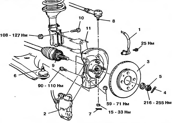
Figure 13.348a. Front wheel hub: 1 - Front wheel speed sensor (for vehicles with ABS); 2 - Brake mechanism support; 3 - Brake disc; 4.7 - Cotter pins; 5 - Nut; 6 - Ball joint; 8 - Tie rod end; 9 - Half shaft; 10 - Bolt with nut; 11 - Hub and steering knuckle
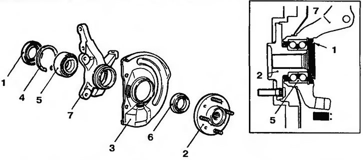
Figure 13.348b. Front wheel hub: 1 - Inner seal; 2 - Hub; 3 - Protective cover; 4 - Snap ring; 5 - Hub bearing; 6 - Outer seal; 7 - Steering knuckle
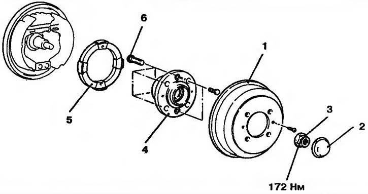
Figure 13.348v. Rear wheel hub: 1 - Brake drum; 2 - Cap; 3 - Nut; 4 - Hub; 5 - Rear wheel speed sensor rotor (cars with ABS); 6 - Bolt
(Information copied from the website: MitsubishiMan.ru)
Checking the axial clearance of the hub
1. Remove the brake caliper and secure it with wire.
2. Remove the brake disc from the front wheel hub.
3. Install a dial indicator and measure the axial clearance by moving the hub in the axial direction (Figure 11.349). Limit value: 0.05 mm.
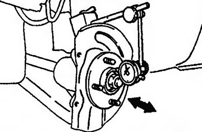
Figure 11.349. Install a dial indicator and measure the axial clearance by moving the hub in the axial direction
4. If the axial clearance exceeds the maximum allowable value, remove and inspect the wheel drive components.