



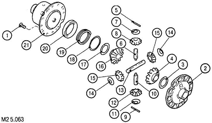
Elements of the rear axle differential lock mechanism design: 1. Screw; 2. Differential housing (A); 3. Intermediate differential adjusting ring; 4. Left axle gear; 5. Pin; 6. Satellite shaft; 7. Washer; 8. Satellite; 9. Pin; 10. Satellite shaft; 11. Washer; 12. Satellite; 13. Satellite shaft; 14. Washer; 15. Satellite; 16. Right axle gear; 17. Intermediate differential adjusting ring; 18. Spring washer; 19. Spring; 20. Drive cam; 21. Differential housing (B)
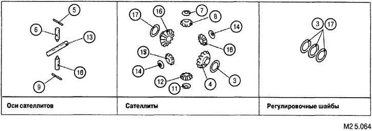
3. Intermediate differential adjusting ring; 4. Left axle gear; 5. Pin; 6. Satellite shaft; 7. Washer; 8. Satellite; 9. Pin; 10. Satellite shaft; 11. Washer; 12. Satellite; 13. Satellite shaft; 14. Washer; 15. Satellite; 16. Right axle gear; 17. Intermediate differential adjusting ring
Disassembly is carried out in the order shown in Fig. M2 5.063, M2 5.064. Assembly is carried out in the reverse order of disassembly.
Adjusting the axle gear clearance
After installing the differential housing (A) and the left axle gear, measure the clearance with a thickness gauge. The standard clearance value is from 0.05 to 0.20 mm. To ensure the standard clearance, use the following adjusting rings.

| 1.1 mm | 1.2 mm | 1.3 mm | 1.4 mm | 1.5 mm |