



Contents: Examination ⤓ Installation ⤓
Remove the gearbox, see paragraph 12.1.
Mark the position of the drive disk on the engine flywheel with a felt-tip pen or a marker.
Lock the engine flywheel by inserting a screwdriver or metal rod into the teeth of the ring gear so that the flywheel cannot turn when the bolts are loosened.
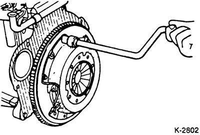
Consecutively, diagonally, each time 1-2 turns, unscrew the bolts securing the driven disk until the springs of the driving disk are released.
Caution: If you loosen all the bolts at once, the diaphragm springs may be damaged.
After this, unscrew the mounting bolts.
Remove the drive and slave disks.
Caution: Remove carefully, avoiding the driving and driven discs from falling, otherwise after installation, malfunctions may occur associated with separation of the discs and jerks when engaging the clutch.
Wipe the engine flywheel with a rag soaked in gasoline.
Caution: The driven clutch disc must not be cleaned. Oil residues must not be removed with detergents.
Examination
Replace oily or mechanically damaged clutch discs.
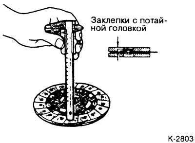
Measure the thickness of the driven disk linings with a caliper. The size to the rivet heads should be at least 0.3 mm, otherwise, the driven disk should be replaced. The same for scratches on the linings.
Check the torsion springs for play and damage; replace the clutch disc if necessary.
Place the driven clutch disc on the gearbox drive shaft and make sure there is no slippage or play in the direction of rotation. To do this, place the disc on the gearbox shaft and move it with your fingers in different directions. If the play is more than 0.4 mm, there is wear on the splines. As a rule, this applies to the splines of the clutch disc.
Move the clutch disc in both directions along the axis. If heavy movement is detected, replace the clutch disc or possibly the gearbox drive shaft.
Check the driven disk for cracks and scratches.
Check the height position of the drive disc diaphragm springs. If the height difference is more than 0.5 mm, replace the drive disc.
Make sure that there are no cracks in the springs connecting the drive disk to the cover, and that the rivets are securely seated. Replace the clutch with damaged or fallen rivets.
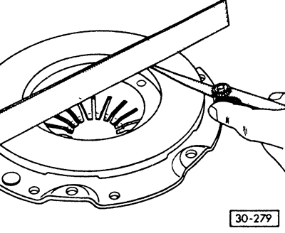
Check the contact surface of the drive disk for cracks, burnouts and wear. Drive disks with an inward deflection of up to 0.3 mm can still be used. Measure with a ruler and a set of feeler gauges.
Installation
Treat the driven disk and engine flywheel with very fine sandpaper.
Clean the splined joint of the driven disk from corrosion and cover it with a very thin layer of MoS ₂ grease. Place the grease in the grooves of the splines and distribute it evenly with a brush.
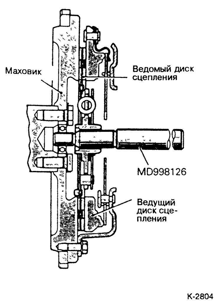
Place the driven and leading clutch discs on the flywheel. The flat part of the driven disc hub should be facing the gearbox, see the picture. Center the driven disc relative to the leading disc by eye. However, it is better to center the discs using a special rod, such as one from HAZET, or an old leading shaft of the gearbox. If the driven disc is not centered, it is impossible to insert the gearbox shaft.
If the old clutch drive disc is reinstalled, observe the markings made during removal.
Tighten the clutch drive disc mounting bolts.
Sequentially, diagonally, each time by 1-2 turns tighten the bolts of the clutch drive disk until the drive disk is tightened. After this, remove the centering rod.
Caution: Make sure that when tightening the mounting bolts, the drive disk enters the flywheel evenly and without scoring. Tightening torque of the clutch drive disk mounting bolts: 20 Nm.
Remove the locking tool from the flywheel ring gear.
If removed, install the release bearing.
Install the gearbox, see paragraph 12.1.